Facebook
 Google
 GitHub
 Linkedin
Q Factor and Bandwidth of a Resonant Circuit
The Q, or quality, factor of a resonant circuit is a measure of the “goodness” or quality of a resonant circuit. A higher value for this figure of merit corresponds to a more narrow bandwidth, which is desirable in many applications. More formally, Q is the ratio of power stored to power dissipated in the circuit reactance and resistance, respectively:
Q = Pstored/Pdissipated = I2X/I2R Q = X/R where: X = Capacitive or Inductive reactance at resonance R = Series resistance.
This formula is applicable to series resonant circuits, and also parallel resonant circuits if the resistance is in series with the inductor. This is the case in practical applications, as we are mostly concerned with the resistance of the inductor limiting the Q.
Note: Some text may show X and R interchanged in the “Q” formula for a parallel resonant circuit. This is correct for a large value of R in parallel with C and L. Our formula is correct for a small R in series with L.
A practical application of “Q” is that voltage across L or C in a series resonant circuit is Q times total applied voltage. In a parallel resonant circuit, current through L or C is Q times the total applied current.
Series Resonant Circuits
A series resonant circuit looks like a resistance at the resonant frequency. Since the definition of resonance is XL=XC, the reactive components cancel, leaving only the resistance to contribute to the impedance.
The impedance is also at a minimum at resonance. Below the resonant frequency, the series resonant circuit looks capacitive since the impedance of the capacitor increases to a value greater than the decreasing inductive reactance, leaving a net capacitive value.
Above resonance, the inductive reactance increases, capacitive reactance decreases, leaving a net inductive component.
NOTE:
At resonance the series resonant circuit appears purely resistive. Below resonance it looks capacitive. Above resonance it appears inductive. Current is maximum at resonance, impedance at a minimum. Current is set by the value of the resistance. Above or below resonance, impedance increases.
Impedance is at a minimum at resonance in a series resonant circuit.
The resonant current peak may be changed by varying the series resistor, which changes the Q. This also affects the broadness of the curve. A low resistance, high Q circuit has a narrow bandwidth, as compared to a high resistance, low Q circuit.
Bandwidth in terms of Q and resonant frequency:
BW = fc/Q Where fc = resonant frequency Q = quality factor
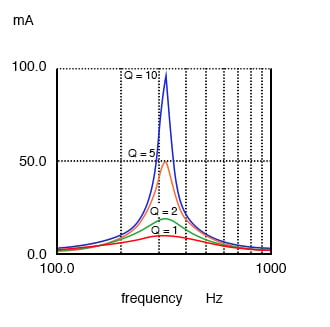
A high Q resonant circuit has a narrow bandwidth as compared to a low Q
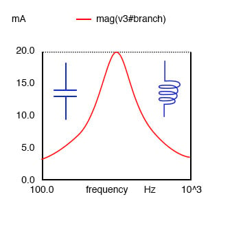
Bandwidth is measured between the 0.707 current amplitude points. The 0.707 current points correspond to the half power points since P = I2R, (0.707)2 = (0.5).
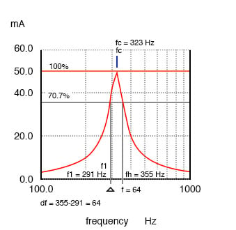
Bandwidth, Δf is measured between the 70.7% amplitude points of series resonant circuit.
BW = Δf = fh-fl = fc/Q Where: fh = high band edge fl = low band edge fl = fc - Δf/2 fh = fc + Δf/2 Where fc = center frequency (resonant frequency)
In the Figure above, the 100% current point is 50 mA. The 70.7% level is .707(50 mA)=35.4 mA. The upper and lower band edges read from the curve are 291 Hz for fl and 355 Hz for fh. The bandwidth is 64 Hz, and the half power points are ± 32 Hz of the center resonant frequency:
BW = Δf = fh-fl = 355-291 = 64 fl = fc - Δf/2 = 323-32 = 291 fh = fc + Δf/2 = 323+32 = 355
Since BW = fc/Q:
Q = fc/BW = (323 Hz)/(64 Hz) = 5
Parallel Resonant Circuits
The impedance of a parallel resonant circuit is maximum at the resonant frequency. Below the resonant frequency, the parallel resonant circuit looks inductive since the impedance of the inductor is lower, drawing the larger proportion of current.
Above resonance, the capacitive reactance decreases, drawing the larger current, thus, taking on a capacitive characteristic.
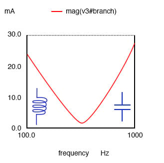
A parallel resonant circuit is resistive at resonance, inductive below resonance, capacitive above resonance.
Impedance is maximum at resonance in a parallel resonant circuit, but decreases above or below resonance. Voltage is at a peak at resonance since voltage is proportional to impedance (E=IZ).
Parallel resonant circuit: Impedance peaks at resonance.
A low Q due to a high resistance in series with the inductor produces a low peak on a broad response curve for a parallel resonant circuit. A high Q is due to a low resistance in series with the inductor. This produces a higher peak in the narrower response curve. The high Q is achieved by winding the inductor with larger diameter (smaller gauge), lower resistance wire.
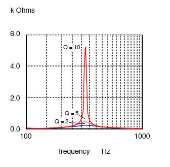
Parallel resonant response varies with Q.
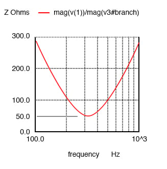
The bandwidth of the parallel resonant response curve is measured between the half power points. This corresponds to the 70.7% voltage points since power is proportional to E2. ((0.707)2=0.50) Since voltage is proportional to impedance, we may use the impedance curve.
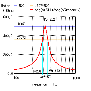
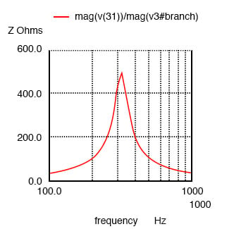
Bandwidth, Δf is measured between the 70.7% impedance points of a parallel resonant circuit.
In the figure above, the 100% impedance point is 500 Ω. The 70.7% level is 0707(500)=354 Ω. The upper and lower band edges read from the curve are 281 Hz for fl and 343 Hz for fh. The bandwidth is 62 Hz, and the half power points are ± 31 Hz of the center resonant frequency:
BW = Δf = fh-fl = 343-281 = 62 fl = fc - Δf/2 = 312-31 = 281 fh = fc + Δf/2 = 312+31 = 343
Q = fc/BW = (312 Hz)/(62 Hz) = 5
RELATED WORKSHEETS: