Facebook
 Google
 GitHub
 Linkedin
Resistors in Parallel: Understanding Current and Voltage in Parallel Networks
This article gives you the information you need to identify parallel resistors and understand their behavior in electric circuits.
Resistors are fundamental electrical components that are found in all types of electrical systems. Furthermore, intentionally installed resistors are not the only source of resistance that we need to account for when we’re designing and analyzing a circuit.
Resistance is everywhere—for example, in conductive wires and traces, integrated-circuit pins, and terminals attached to capacitors and inductors. Understanding resistance is an essential step toward understanding electronics.
Resistors in Parallel
The many sources of resistance that influence the operation of a circuit can combine in various ways. One of the two most important resistor configurations is called parallel.
We say that resistors are in parallel when the terminals of one resistor are connected to the same two nodes as the terminals of another resistor.
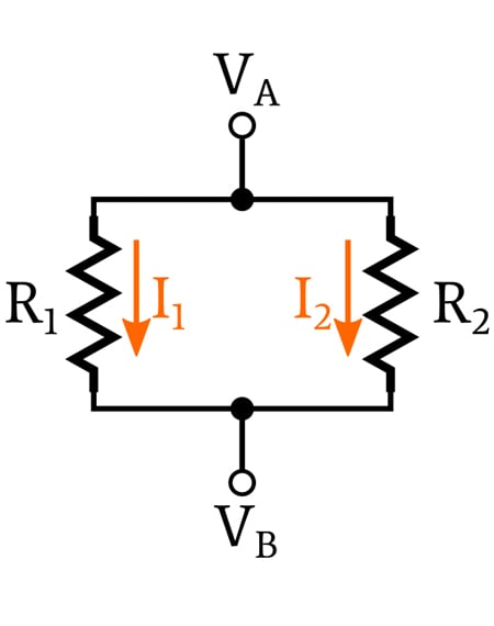
A Resistors in Parallel Circuit
Consider the diagram below.
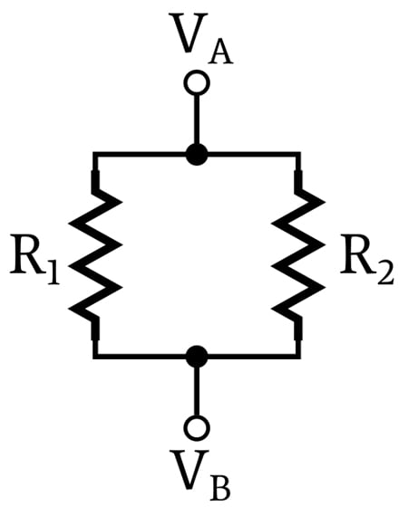
These two resistors are in parallel.
The upper terminal of R1 and the upper terminal of R2 are connected together by an idealized wire that has zero resistance, and the two lower terminals are connected together in the same way. This means that the two upper terminals have the same voltage, namely, the node voltage VA, and that the two lower terminals have the same voltage, namely, the node voltage VB.
Thus, we say that the voltage across each resistor is the same:
\[V_{R1} = V_{R2} = V_A – V_B\]
Parallel Resistance Equation
Before moving on, you can check out AAC's parallel resistance calculator for more information on parallel resistance.
Shared Voltage
The voltage relationship described above is not merely an interesting characteristic associated with parallel resistors. Rather, it is the fundamental characteristic of parallel resistors: if resistors are connected between the same two nodes, the voltage across each resistor is the same, and the resistors are in parallel.
It is important to understand that the criterion of shared voltage, meaning connection between the same two nodes, is the only reliable way to identify parallel resistors.
In fact, the term “parallel” can be misleading.
Resistors in Parallel—Examples
In many cases, parallel resistors are indeed drawn like two parallel lines; however, resistors drawn in a parallel configuration may not be electrically in parallel, and we often come across resistors that are electrically in parallel but are not drawn in a parallel configuration.
Let’s take a look at some examples. Are these resistors in parallel?
Yes, they are, because the left-hand terminals of both resistors are connected to the same node, and the right-hand terminals of both resistors are connected to the same node.
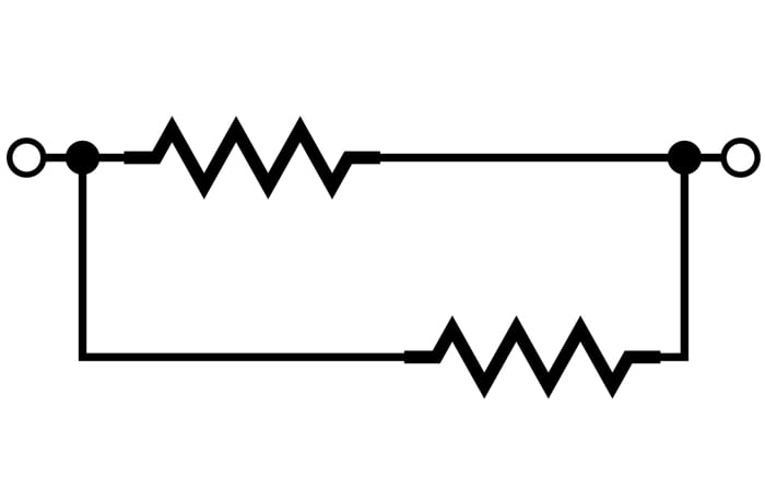
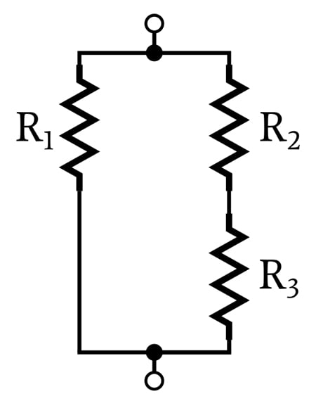
The following two diagrams also contain parallel resistors; don’t let the physical configuration distract you from the fact that the voltage across the two resistors is the same.
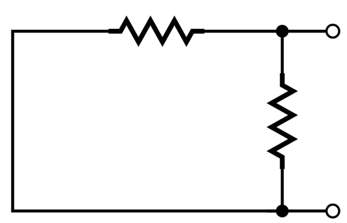
In the following diagram, are R1 and R2 in parallel?
We do have two parallel current paths in this configuration, but R1 and R2 are not in parallel because they aren’t connected between the same two nodes. Rather, we can say that R1 is in parallel with the combined resistance of R2 and R3.
Let’s look at one more example. Are these parallel resistors?
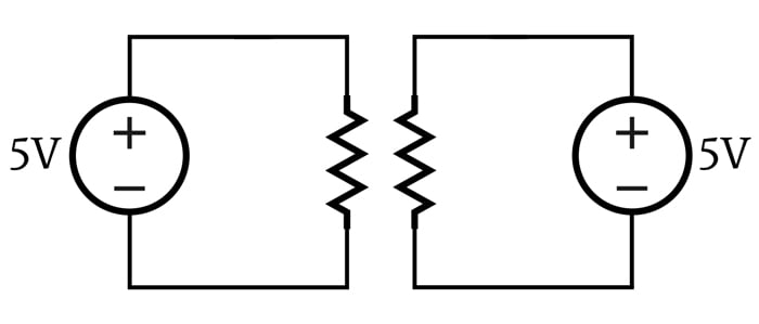
They’re not, and here’s why: The voltage across these two resistors has the same numerical value (5 V), but it is not the same voltage, because the two resistors are connected to two separate voltage sources.
My intention with this example is to emphasize the fact that parallel resistors must be connected between the same two nodes. Resistors in parallel have the same numerical voltage drop because they are connected between the same two nodes. If they are connected between different nodes, they are not in parallel, even if they look like they’re in parallel and have the same numerical voltage across them.
Current in Parallel Resistors
At this point we know that the voltage across parallel resistors is the same, but what can we say about the current flowing through parallel resistors?
We cannot apply a simple, generalized rule that gives us specific information about the currents flowing through parallel resistors, because each branch of the parallel circuit is independent. We use the term “branch” to specify one of the current paths that exists between the two shared voltage nodes.
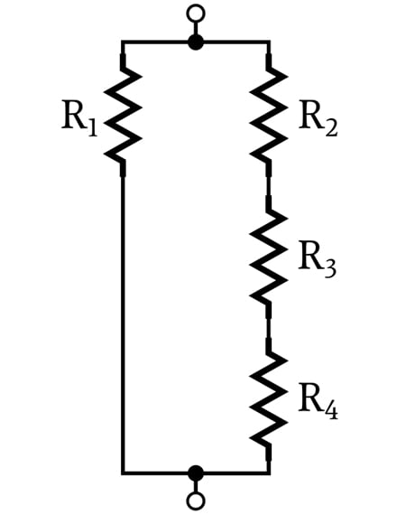
In the previous diagram, R1 forms one branch between VA and VB, and R2 forms a second branch. The next diagram also has two branches, but the second branch consists of three resistors (R2, R3, and R4).
The current of each branch is determined by the resistance of the branch and the voltage across the branch. There is no fixed relationship between branch currents in a network of parallel resistors.
Dividing Current
Two resistors in series can function as a voltage divider. The total voltage applied to the network is divided between the two resistors, and the designer can use the node between the two resistors to produce a desired voltage.
Parallel resistors have an analogous effect with current: the total current flowing into the network is divided between the parallel branches. Branches with higher resistance will have a smaller proportion of the total current, and branches with lower resistance will have a larger proportion of the total current.
Summary
Resistors are in parallel when they are connected between the same two nodes. It follows that resistors in parallel have the same voltage across their respective terminals. The different parallel current paths leading from one node to another are called branches, and a branch can consist of one or multiple resistors.
The amount of current flowing through a branch depends on the resistance of the branch and can be calculated using Ohm’s law.
In the next article, we will explore mathematical aspects of parallel networks, including how to calculate the equivalent resistance of resistors that are connected in parallel.