
 Facebook
 Google
 GitHub
 Linkedin
Intel’s 2716 and 2732: The EPROMs That Put Firmware on a Single 5 V Rail
Intel’s 2716 and 2732 took UV EPROMs from “power-supply problem” to practical, socketable firmware for mainstream 8-bit and early 16-bit designs.
By the mid-1970s, EPROMs had already proven that it was possible to ship a system with read-only code, then change that code without creating new masks. The catch was that many early EPROMs still behaved like lab parts. The Intel 2708, for example, worked, but it asked for +5 V, +12 V, and -5 V just to read, plus a c. 25-V programming pulse.
The 2716 and 2732 were where EPROMs started to feel like a normal component. They were still UV-erasable, still required a high voltage to program, and still featured that iconic quartz window. However, for everyday read operations, they simplified the design by collapsing the mess down to a single +5-V supply, adding standby modes, and introducing control pins that made bus-based microprocessor systems far less painful.
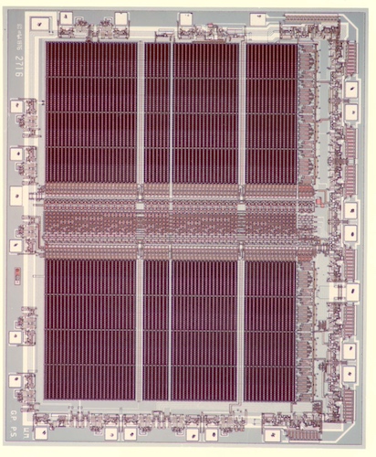
The 2716 EPROM. Image used courtesy of Intel
From Three Rails to One
Intel, in its original component literature, bluntly described the 2716 as a 16,384-bit EPROM that “operates from a single 5-volt power supply,” includes a “static standby mode,” and targets faster microprocessor systems. Intel explicitly namechecks the 8085 and 8086 families in that context.
That single-rail read was more important than it sounds. Once your firmware store no longer demanded extra regulators and bias rails, EPROM stopped being a special case and became something you could sprinkle across a board as boot code, monitor ROM, character generators, lookup tables, or whatever else needed to survive power-off.
The 2716 also established the workflow most engineers remember as the EPROM workflow: program electrically, erase optically, and repeat. Programming was byte-wide, with a 25-V VPP and a program pulse on the enable pin lasting tens of milliseconds; 45–55 ms was a typical spec for the part family.
Crucially, Intel treated these EPROMs as development parts you could later swap for cheaper production ROMs without redesigning your board. Ultimately, the company pitched the 2716 as a prototyping stepping stone to pin-compatible ROMs like Intel’s 2316E.
The 2732
While the 2716 dramatically simplified the EPROM and arguably made it a sane component, the 2732 added space, featuring a 32,769-bit device (4,096 x 8). It also included a single +5 V for reads, standby support, a separate output enable control, and, most notably, “output enable”.
Once microprocessor designs got serious about shared buses and multiple memory devices, it wasn’t enough to simply select a chip. You needed to control when its outputs were actually driving the data bus. The 2732’s output enable functionality allowed engineers to gate outputs independently and avoid contention in multi-device systems.
Intel also framed the 2732 as a bridge to volume production in the same way as the 2716: prototype in EPROM, then drop in a pin-for-pin ROM once the code was stable. In the 1979 component catalog, Intel called out using the 2732 for prototyping and the 2332A ROM for production—“pin for pin compatible… in all respects.”
Programming still carried some old-school sharp edges. The 2732 was in programming mode when its OE/VPP pin was at 25 V, and Intel required a 0.1-µF capacitor across OE/VPP to ground to suppress transients that could damage the device. Then came the 2732A, which retained the same basic identity but modernized the details engineers cared about day to day, such as faster access options (down to 200-nanosecond variants), lower standby current (35 mA max vs 150 mA active), and a lower programming voltage (21 V instead of 25 V).
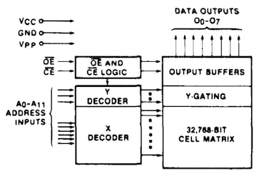
Block diagram of the 2732A. Image used courtesy of Retro-kit
That speed increase wasn’t empty marketing talk, either; Intel explicitly pitched the faster 2732A variants as compatible with high-performance CPUs like the 8-MHz 8086-2, enabling operation without adding wait states in some system designs.
Two Quirky Parts
To say the 2716 and 2732 were quirky would be an understatement, and those who used them will have not-so-fond memories of the sheer amount of frustration they could bring.
One of the biggest sticking points was that EPROMs will eventually erase under the wrong lighting conditions, and Intel’s own erasure notes for the 2732A point out that constant exposure to room-level fluorescent lighting could erase a typical device in about three years, and direct sunlight could do it in roughly a week. The fix for this was pretty on-brand for the EPROM era: put an opaque label over the window and call it a day.
Other issues tended to exist around programming conditions and pin behavior. The 2732A documentation is explicit about what not to do—don’t “program… with a DC signal applied to the CE input”—and it repeats the need for that 0.1-µF decoupling across OE/VPP during programming.
But perhaps the biggest challenge was compatibility. The 2716 and 2732 share the same 24-pin physical format, and both became so common that board designers and repair techs developed an entire subculture of adapter boards, half-capacity substitutions, and “it works if you strap this pin” hacks. Intel’s own catalogs encouraged a different, more disciplined kind of compatibility: EPROM for development and ROM for production, with pin-for-pin swaps as part of the plan.
And that’s what made these EPROMs so notable. They didn’t just add bits; they normalized the idea that firmware was a living artifact during development and a fixed artifact in shipping hardware. You could move between those worlds without redesigning your system every time the code changed.








I extensively used the 2758 even easier.
I love these articles, keep ‘em coming!