 Facebook
 Google
 GitHub
 Linkedin
Ground and Other Reference Points
Video Lectures created by Tim Feiegenbaum at North Seattle Community College.
We are in the final section of chapter four, 4.6 Grounds and Other Reference Points.
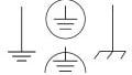
In most circuits, there is one common point which all circuit values are measured. Typically, this point is called the circuit ground. Usually, it looks kind of like that. In all cases, ground is considered to be zero volts and is typically one side of the circuit's power source.
Grounds
The two circuits below are electronically the same, the schematic to left shows the complete loop for current flow. Here, you will see the complete loop which is an expectation for all electronic circuits. You must have a complete loop to support current flow.
The circuit to the right has eliminated the lower wire and replaced it with an additional ground. You notice here that the wire across the bottom has been eliminated and it is placed in another ground here. For electrical purposes, there may be multiple grounds like represents the same point. This simplifies the schematic drawing. You will commonly see a schematic drawing rather than run this wire all the way across the page to a common single ground point. They will just show multiple grounds but it is understood that they all represent the same point.
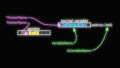
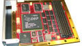
Circuit boards will normally contain a ground plane to which all ground connections are made. Circuit boards usually have several layers. This one layer is frequently made of solid copper and is dedicated to providing ground connections for all other layers. Here, we see a ground plane for a circuit board.
Non-Ground References
In some cases, the voltage is measured that is the reference to a point other than ground. So if you're measuring point A, the reference point would be ground. So here, if we measured from point A to ground, we got 21 volts. But sometimes, you want to measure a voltage reference to a point other than ground so sometimes you might see something like this, VAB. In this case, you will be looking, for example, the voltage between Point A and Point B; in this case, you will measure five volts. You commonly see it like this where A is the measured point while B represents the reference point, so AB will be five volts.
The voltage potential for non-ground reference is the algebraic sum of the two points. If you measured from A to B, it would be five from A to C it would be nine and so forth.
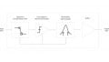
Voltage measurement with respect to ground. Now, here we have a circuit that is drawn a little bit different than you might expect. We usually expect to see the ground at the bottom of the power supply but in this case, the ground has been placed at another point in the circuit. For electrical purposes, for purposes of voltage drops and for purposes of current, there will be no change in the circuit because we still have a series circuit, we still have all our components, we still have our power supply, we still have ground. This ground was placed at a different point. What will this impact is that if we're measuring our voltage in respect to ground, we'll see some different values.
Here, we have 20 volts supplied and if I measure from Point A to ground, I'm not going to measure 20 volts. I'm going to measure about 13 volts from here to our point of ground. If I'm going to measure C to ground, I'm going to measure six volts. If were in reference to ground and we're going to see different values then we'd expect that the ground is going to be placed here.
We will certainly see some things differently if we measure e.g. Point D to ground. In this case, we are actually going to measure a minus 2 volts if we have a voltmeter connected so the common probe goes to ground, voltage probe goes to D and we would see minus 2 and here, we would see minus 7 volts. With that, we would begin using the electronics workbench, we would be able to build a circuit like this and we would be able to measure those quantities and prove that is, in fact, the case.
This is our final section in chapter four and we've been talking about grounds and non-ground reference points and we looked at a ground plane on a circuit board. We looked at the fact that typically on circuit schematics that returning the line to a single ground point is usually eliminated. We might see many ground points on a schematic but then they are all electrically the same point. That concludes our discussion on Ground.
Related Content


All interesting stuff, but doesn’t quite explain what the ground connection does in the circuit.