 Facebook
 Google
 GitHub
 Linkedin
Troubleshooting Open and Shorted Series Circuits
Video Lectures created by Tim Feiegenbaum at North Seattle Community College.
Troubleshooting is a process whereby you diagnose a malfunctioning system and identify the specific defect. Once the defect is identified, a judgment must be made regarding the feasibility of repair and there are a number of considerations that have to be made. One is the time, how it will take to repair this. Sometimes there are critical systems that there is no time to repair them and simply replace the entire circuit board and just to continue to use the system. There is the time involved and also there a cost because when you go to repair a system, there is going to be the wage a person repairing it, the cost of the components to make it work, so there are considerations to be made, is it going to cost more to fix this than simply to replace it.
This chapter examines troubleshooting strategies and techniques. Troubleshooting is a lot of fun for those people that make a career, out of doing this and they can be a rewarding career. People in our electronics program in North Seattle, many students will go out into the industry they worked in, biomedical repairs, some work in telecom, some work in broadband, industrial power and for the most part, they are maintaining and repairing electronic systems that we come to depend upon in our daily lives.
Troubleshooting Series Circuits
This particular section 5.1, we're going to do it in two parts. Peer series circuits are rare and practical electronics system. You don't commonly see a disappear series circuits. However, what you will see are parts of circuits that are series within a given system but usually, an entire system isn't just a series circuit. You did not know how to troubleshoot them because you will find a series of circuits within systems.
Troubleshooting strategies applicable to series circuits play a major role in troubleshooting advance circuit configurations.
Basic Concepts
Logical troubleshooting procedures will aid in analyzing and troubleshooting all circuits, simple or complex.
Three goals of a troubleshooter should be:
- Make a measuring only if you know what a good reading should be. The idea here is that you can make all kinds of measurements but if you don't know what the correct measurement should be, you're probably just wasting your time.
- Make as few measurements as possible. The idea here is not to waste your time.
- Select the best tool for the task at hand. Typically, electronic troubleshooting tools would be things like Oscilloscopes and volt readers. Depending on the task, if you're out in the broadband industry, you'll probably want signal level meters. There is wide variety of tools out there that might be appropriate for a given task.
Know what is normal in a circuit. There are a number of sources to get this information. The first we will mention is a schematic. A schematic is just a printed readout of the circuit configuration where you could look at each component on paper and view the overall circuit. This is one of the primary troubleshooting tools many times the schematics will have voltages written in so that you'll know what you should read at specific points.
Another good way to know what is normal is to have a good known circuit for comparison. Let's say if I have a box here and we'll call this a bad one and here is the good one and let's pretend that we have a troubleshooting points or voltages that we are measuring and we suspect that something is wrong. Here, we could measure the known good box and make a determination whether there is something wrong or not. So, a known good circuit is a good way to know what is normal in a given circuit.
Finally, there is simply an intuitive understanding. Intuitive understanding usually comes with time a given technician will be able to work in a box, look at it and intuitively he'll have a sense of what is wrong oftentimes based upon his experience.
Intuitive Troubleshooting
Developing a solid intuitive understanding of a circuit behavior is important to becoming a skilled troubleshooter. There are some general rules that form the basis for all troubleshooting efforts. These are the effective power supplies, open circuits, short circuits and components which values have changed or important to understand.
Effects of an Open Circuit
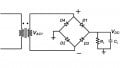
First, we are going to look at the effects of an open circuit. Open circuits are characterized by having infinite resistance. In this case, we're considering resistance and open circuits will have infinite resistance. The circuit here, were looking at, have a component showing a resistor that is open. Commonly what causes this is too much current has flowed through the circuit and this particular component may have disintegrated, burned up and you will see a charred component. If you were to measure test point 4 to test point 5 with an Ohmmeter, you will commonly expect to see infinite resistance. This component seizes to exist because it's simply burned up.
Typically, you will expect to see infinite resistance but that wouldn't always be the case because sometimes when you measure the surface, you will think that you are measuring across here. What actually is happening is that the Ohmmeter doesn't know what you are just measuring across. It may measure around like this, and you may get a resistance. It may be rather measure a high one but it may not necessarily, be infinite because it may measure a different path through the circuit.
An open circuit will appear to have the applied voltage across it. The things that often surprise students is they go in … now this is what you're measuring, voltage. When they measured resistance, the circuit was turned off. When they measured voltage, we have power applied when they measure test point 4 to test point 5. Rather than seeing zero volts, we oftentimes times see, in a case like this, you might read 25 volts. People will wonder why. Consider the fact that proven the circuit is operating correctly; we have a current flowing through the circuit. We have that loop which is a requirement for all circuits. When this component opens, we no longer have that loop. So now, there is no current flowing through this component and you might notice the little zero here, on all these components indicating zero volts. Well, why is there zero volts?
Let's remember Ohms law, voltage=current x resistance. If the resistance has remained unchanged but now the current is zero, so zero times the resistance is going to equate to zero volts. In this circuit, there are no voltage drops across these components. When I insert my meter into the circuit, I will measure the supply voltage because there are no drops and any point in this circuit.
If the open circuit appears between a monitor point and ground, the meter will read a source voltage, otherwise it will be zero. When you're measuring something like this, you'll have your meter and a probe going to ground the other probe. In that situation is what we just previously described that in case, I will read the supply voltage.
There's a note down here. If the circuit is open, how much current is flowing? None. How much voltage will be dropped across each resistor? Zero. What voltage will it measure across the open? That's the power supply voltage.
Effects of Short Circuit
The previous screen you looked at the effects of an open. We're going to look at the same circuit and we're going to look at what happens if we have a short.
A short is characterized by having a zero resistance or very low resistance. Again, if the circuit is turned off and we are measuring resistance, then we measure from this point to this point, we're going to measure … this is the case of a short, either a very low resistance or zero resistance.
When a short circuit occurs within a series component; others components in the series have higher currents. In this entire circuit, we have a … maybe I'll put an R or T here, for total resistance. Remember, that current = voltage/resistance. If this component shorts, the total resistance is going to decrease and so the current in the circuit will increase. This blue arrows, here, that have a little V tied to them. This is indicating that the voltage across this voltage will suddenly be a little bit higher. The reason that the voltage is a little bit higher is because one of the resistors has been removed, shortage across, so the resistance has gone down, current has gone up and so all the voltages have increased a little bit. When a short circuit occurs within series component, other components in the series will have higher currents which we've shown. The voltage across a short circuit is zero. Now, if we measure voltage and place a volt meter in the circuit, measure it form here to here, remember it is a short we will measure zero volts.
The best tool for diagnosis is a VOM. With a VOM or volt ohmmeter, you can measure the voltage and the Ohms. The resistance across R4 is zero ohms. The voltage across R4 zero volts. The current through the short … current increases because R4 is not on the circuit. We've mentioned all of that over here.
This is the same schematic and this is review. With force shortage, there will be an increasing current. The blue arrows indicated a larger voltage across every component because of increased current. Therefore, the voltage read across every component will increase.
The voltage read across every component with respect to ground will measure closer to the applied voltage. I mention this because, in the summary statements in this chapter, they make mention of the fact that the voltage across every component will measure closer to the applied voltage. They wouldn't measure the applied voltage but since every voltage increases, they will be closer to that applied voltage.
In this section, we introduced troubleshooting, we looked at the effects of short circuit and we looked at the effects of an open circuit. We talked briefly about intuitive troubleshooting, the goals of troubleshooting and what is normal and how to determine what is normal in a given circuit.
Related Content


I like the idea of good operating circuit values as a guide on what to look for in a bad circuit. In fact, I thought about it today. Excellent. Yes just check how a normal operating system reads and does in different settings and it is a good effective overall approach.