 Facebook
 Google
 GitHub
 Linkedin
Troubleshooting Series and Parallel Circuits
Troubleshooting a Series and Parallel Circuit
The jobs of electronics engineers and technicians frequently entail troubleshooting malfunctioning circuits to locate and correct a problem. We will explore some of the effects of resistor failures in both series and parallel circuits.
The jobs of electronics engineers and technicians frequently entail troubleshooting malfunctioning circuits to locate and correct a problem. Good troubleshooting is a demanding and rewarding effort that requires numerous skills, including:
- An understanding of basic electronics concepts
- The ability to formulate hypotheses (proposed explanations of the problem)
- The ability to judge the value of different hypotheses based on their probability (how likely one particular cause may be over another)
- Creativity in applying a solution to rectify the problem
While it is possible to distill these skills into a scientific methodology, most practiced troubleshooters would agree that troubleshooting involves a touch of art that can take years of experience to develop fully.
An essential skill to have is a ready and intuitive understanding of how component faults affect circuits in different configurations. Here, we will explore some of the effects of component faults in series and parallel circuits.
How to Troubleshoot Short a Circuit in a Series Circuit
Let’s start with the simple series circuit (Figure 1), which consists of a 9 V battery and three resistors in series.
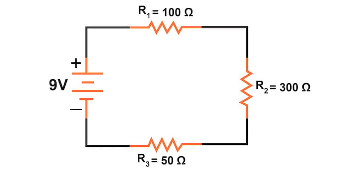
Figure 1. Series circuit example without failures.
With all components in this circuit functioning at their proper values, we can employ Ohm’s law table method to determine all of the currents and voltage drops, as shown in Table 1.
Table 1. The Ohm’s law table method is applied to the series circuit of Figure 1.
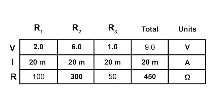
The values in regular font are the terms that can be filled directly from the circuit. The bold values are calculated using Ohm’s law and the rules for series circuits.
Now let us suppose that resistor R2 fails as a short circuit, as illustrated in Figure 2. A short circuit means that the resistor now acts as a straight piece of wire with little or no resistance. What causes the shorted condition of R2 does not matter to us in this example; we only care about its effect on the circuit. The circuit will behave as though a jumper wire were connected across R2. If you were wondering, a jumper wire is a common term for a temporary wire connection in a circuit.

Figure 2. Series circuit with a short circuit of resistor R2.
The total circuit resistance will decrease with R2 shorted. Since the voltage output by the battery is a constant 9 V (at least in our ideal example), a decrease in total series circuit resistance means that the total circuit current must increase.
Let’s recalculate the circuit voltages, currents, and total resistance, as shown in Table 2.
Table 2. Recalculating the circuit V, I, and R after the shorting of resistor R2.

With the increase of the circuit current from 20 to 60 mA, the voltage drops across R1 and R3 (which haven’t changed resistances) increase as well, so that the two resistors are dropping the whole 9 V. R2 is effectively eliminated from the circuit with the resistance from one lead to the other having been reduced to zero. Thus, the voltage drop across R2, even with the increased total current, is 0 V.
Now, let’s apply this change in circuit behavior to troubleshooting. If the circuit current is higher than expected, look for a short circuit in one or more of the components. Measuring the voltage across each component can help identify the short's location. The short-circuited component will have a very low voltage drop across it.
Causes of short circuits can include:
- Device failure
- Moisture damage
- Solder migration
- Shorted Components in a Series Circuit
Troubleshooting Open Circuits in Series Circuits
Another type of electronics component failure is an open circuit failure where resistance increases to nearly infinite levels. If R2 were to fail open, it would create wide-reaching effects in the rest of the circuit, as illustrated in Figure 3.

Figure 3. Series circuit with open circuit failure of resistor R2
We will again use our Ohm’s law table method to calculate the resulting circuit current and voltage drops (Table 3).
Table 3. Recalculating the circuit V, I, and R with an open circuit failure of resistor R2

With R2 at infinite resistance, the total series circuit is now also infinite. Therefore, the total current decreases to zero. With zero circuit current, there is no current to produce voltage drops across R1 or R3. R2. On the other hand, this will manifest the full supply voltage across its terminals.
Based on these results, we can apply this lesson to troubleshooting. If we observe a circuit current that is much too low or even zero, we can deduce that there is an open circuit somewhere within the circuit. Using a voltmeter, we could find the component or section of the circuit that has all or most of the voltage dropped across it; this will be the location of the open circuit.
Open circuit failures can be caused by broken connections due to vibration, shock, or device failures.
How to Troubleshoot a Short Circuit in a Parallel Circuit
We can apply the same before and after analysis techniques to troubleshoot parallel circuits that we used in the previous section.
First, we will start by determining how the “healthy” parallel circuit of Figure 4 should behave.
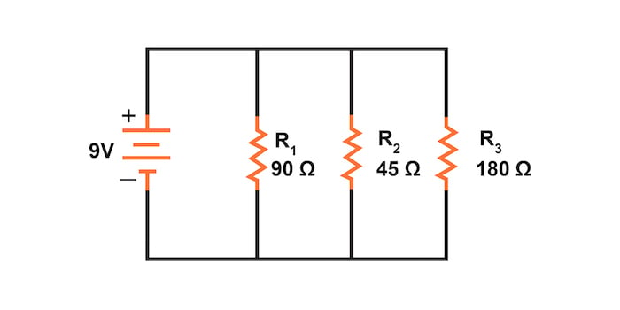
Figure 4. Parallel circuit example without failures.
We calculate the unknown circuit parameters by carefully applying Ohm’s law and the rules for parallel circuits to arrive at the results shown in Table 4. The values entered directly from the circuit are in regular font, while the calculated values are in bold.
Table 4. Application of the Ohm’s law table method to the parallel circuit of Figure 4.

In an ideal case (with perfect voltage sources and zero-resistance connecting wire), shorted resistors in a simple parallel circuit will have no effect on what’s happening in the other branches of the circuit. In real life, the effect is not quite the same, and we’ll see why in the following example circuit of Figure 5.

Figure 5. Parallel circuit with a short circuit of resistor R2.
A shorted resistor (resistance of 0 Ω) would theoretically draw infinite current from any finite voltage source because I = V/0. In this case, the zero resistance of R2 also decreases the circuit's total equivalent resistance to 0 Ω and increases the total current to a value of infinity (Table 5).
Table 5. Recalculating the circuit V, I, and R with an open circuit failure of resistor R2.
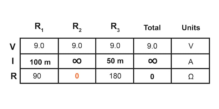
As long as the voltage source holds steady at 9 V while supplying infinite current, the other branch currents, through resistors R1 and R3, will remain unchanged.
Realistic Parallel Circuit Operation in the Presence of a Short Circuit
However, the critical assumption in this “perfect” scheme is that the voltage supply will hold steady at its rated voltage while supplying an infinite amount of current to a short-circuit load. This is simply not realistic. Even if the short has a small amount of resistance (as opposed to absolutely zero resistance), no real voltage source could arbitrarily supply a huge overload current and maintain the steady voltage simultaneously.
This situation is primarily due to the internal resistance intrinsic to all electrical power sources, stemming from the inescapable physical properties of the materials they’re constructed of, as illustrated in Figure 6.
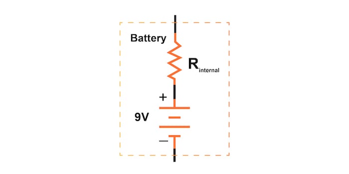
Figure 6. The internal resistance of a voltage source.
These internal resistances, small as they may be, turn our simple parallel circuit into a series-parallel combination circuit. Usually, the internal resistances of voltage sources are low enough to be safely ignored, but when high currents resulting from shorted components are encountered, their effects become very noticeable.
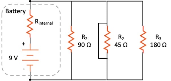
In our more complex circuit of Figure 7, a shorted R2 would result in almost all the voltage being dropped across the internal resistance of the battery, with almost no voltage left over for resistors R1, R2, and R3.

Figure 7. The realistic voltage source in a parallel circuit with a short circuit.
Often, we will not know the exact internal resistance of the voltage source. Thankfully, we can proceed with the circuit analysis with only estimates. Table 6 has been filled out using general, qualitative estimates instead of specific values. Because of the short circuit of resistor R2, we know the voltage across all three resistors will be low. We also know that most of the current will pass through R2. Therefore its current will be high, but the other branch currents will be low.
Table 6. Estimating voltages and currents with a short circuit in a parallel circuit.

Whereas the normal application of Ohm’s law and the rules of series and parallel circuits is performed with numerical quantities (“quantitative”), this kind of analysis, without precise numerical figures, is something we’d like to call “qualitative analysis.” In other words, we can analyze the qualities of the effects in a circuit rather than the precise quantities. The result, for you, will be a much deeper intuitive understanding of electric circuit operation. It also allows us to proceed with our troubleshooting without having precise numerical values.
It is sufficient to say intentional direct short circuits across the terminals of any voltage source are a bad idea. Even if the resulting high current (heat, flashes, sparks) causes no harm to people nearby, the voltage source will likely sustain damage unless it has been specifically designed to handle short circuits, which most voltage sources are not.
Troubleshooting Open Circuits in a Parallel Circuit
Now, let’s examine an open circuit in our parallel circuit of Figure 8.

Figure 8. Parallel circuit with open circuit failure of resistor R2.
We can now repopulate our Ohm’s law table, as shown in Table 7.
Table 7. Recalculating the circuit V, I, and R with an open circuit failure of resistor R2.
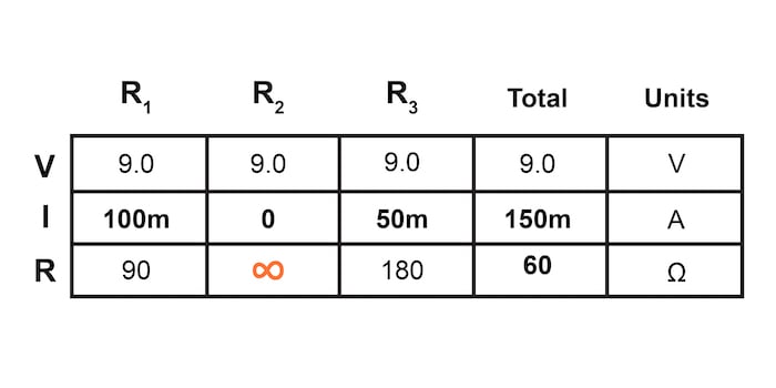
Notice that in this parallel circuit, an open branch only affects the current through that branch and the circuit’s total current. The total voltage of 9 V is shared equally across all components in a parallel circuit and will be the same for all resistors.
Since the voltage source’s tendency is to hold the voltage constant, its voltage will not change. In addition, since the voltage is the only common parameter in a parallel circuit and the other resistors haven’t changed resistance value, their respective branch currents remain unchanged.
Household Lighting Example of a Parallel Circuit
In household lighting, all of the lights get their operating voltage from power wiring arranged in a parallel fashion, as shown in Figure 9. Turning one lamp off creates an open circuit in that branch of the circuit.

Figure 9. Parallel circuit with open circuit failure of resistor R2.
The opening or closing of one branch in this parallel circuit doesn’t affect the operation of other lights in the room; it only changes the current in that one light (branch circuit) and the total current powering all the lamps in the room.
Troubleshooting Series and Parallel Circuits Review
The ability to intuitively determine what will happen to a circuit with any given component fault is a crucial skill for any electronics troubleshooter to develop. The best way to learn is to experiment with circuit calculations and real-life circuits, paying close attention to what changes with a fault, what remains the same, and why.
- A shorted component is one whose resistance has dramatically decreased, typically near zero.
- An open component is one whose resistance has dramatically increased.
- To determine what would happen in a circuit if a component fails, re-draw that circuit with the equivalent resistance of the failed component in place and recalculate all values.
- For the record, resistors tend to fail open more often than fail shorted, and they rarely fail unless physically overstressed (drops, vibration, moisture, temperature) or electrically overstressed (voltage or current).
Related Content
Below you can find more resources on troubleshooting and parallel and series circuits:
Calculators:
Worksheets:
- Basic Circuit Troubleshooting Worksheet
- Basic Troubleshooting Strategies Worksheet
- Series DC Circuit Practice Worksheet
Video Tutorials and Lectures:
- Troubleshooting Open and Shorted Series Circuits
- Troubleshooting Strategies
- Troubleshooting Series-parallel Circuits
- Troubleshooting Series Circuits
- Troubleshooting Parallel Circuits
- Troubleshooting Semiconductors
Technical Articles:
- Resistors in Parallel: Understanding Current and Voltage in Parallel Networks
- Measuring Resistance, In Circuit and Out
- Add Short Circuit Protection to Your Boost Converter


In the section under “Analyzing Failures on a Simple Parallel Circuit” I believe you mislabeled the 6V voltage source as being 9V in the box diagram.
I believe that there is a mistake in the paragraph that conclude the troubleshooting of an open circuit in a series circuit
“Based on these results, we can apply this lesson to troubleshooting. If we observe a circuit current that is much too low or even zero, we can deduce that there is a short circuit somewhere within the circuit. Using a voltmeter, we could find the component or section of the circuit that has all or most of the voltage dropped across it; this will be the location of the open circuit.”
Instead of “we can deduce that there is a SHORT circuit somewhere” it has to be “we can deduce that there is a OPEN circuit somewhere”