 Facebook
 Google
 GitHub
 Linkedin
What Is a Voltage Drop in an Electric Circuit?
How exactly does polarity factor into the voltage drops across the three basic elements of electrical circuits—resistors, capacitors, and inductors?
In this Frequent Engineering Question, we'll give a brief conceptual explanation of voltage drops and discuss the polarity of voltages dropped across resistors, capacitors, and inductors.
Voltage, Work, and Current Flow
A battery converts chemical energy into electrical energy, producing a voltage—i.e., a difference in electric potential—across its two terminals. A resistor is a component that creates a specified amount of resistance to electric current. When we connect the two terminals of a resistor to the two terminals of a battery, charge carriers move through the circuit, and we call this electric current.
Voltage conveys the ability to do the work of moving charge from one point to another. A 5 V battery, for example, can do 5 joules of work per coulomb of charge. When current is flowing through a resistor, we can measure the amount of work (per unit charge) required to keep the current flowing through the resistor.
This is the essence of voltage drop: a battery (or voltage source) supplies energy for doing the work of moving charge. When current is flowing, components such as resistors consume energy, and the amount of work per unit charge associated with the current flowing through a given component is the component’s voltage drop.
The voltage dropped by a component accounts for a portion of the voltage generated by the battery. In other words, the work performed by the battery is divided up among the components in the circuit.
We can intuitively recognize that driving a given amount of current through more resistance will require more work. Thus, if two resistors are in series (meaning that they have the same current flow), the resistor with more resistance has a larger voltage drop. This is the basis for the operation of the voltage divider circuit.
Polarity of Voltage Drops
A resistor always functions as a load—that is, as a component that consumes energy. If we adopt the conventional current flow model, in which current flows from higher voltage to lower voltage, the voltage drop across a resistor is positive where the current enters the resistor and negative where the current exits the resistor:
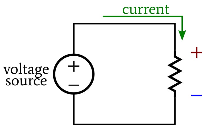
A current flow model depicting how a voltage drop is positive where current enters a resistor and negative where it exits.
This polarity “opposes” the source voltage: if we connected a battery with this same polarity orientation, it would drive current in the opposite direction (or it would counteract the source voltage, depending on how you think about it).
Capacitors and inductors store energy, and consequently, they can function as either a load or a source. When they are acting as loads, they have the same voltage-drop polarity as a resistor.
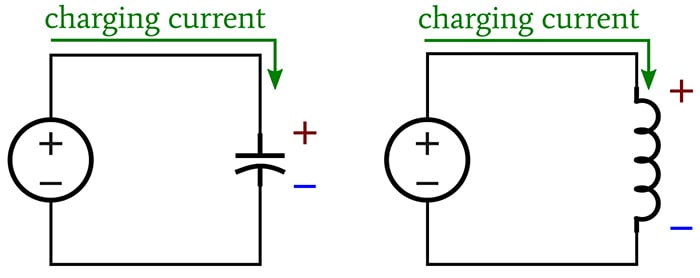
When acting as loads, capacitors and inductors have the same voltage-drop polarity as a resistor.
The voltage-drop polarity of a capacitor doesn’t change when it begins to discharge. Even though it is acting as a source, it produces current whose direction is opposite to that of the charging current.
However, when an inductor discharges, it attempts to maintain current flow. Thus, the polarity of the inductor’s voltage drop changes, because it is generating current whose direction is the same as that of the charging current produced by the source.
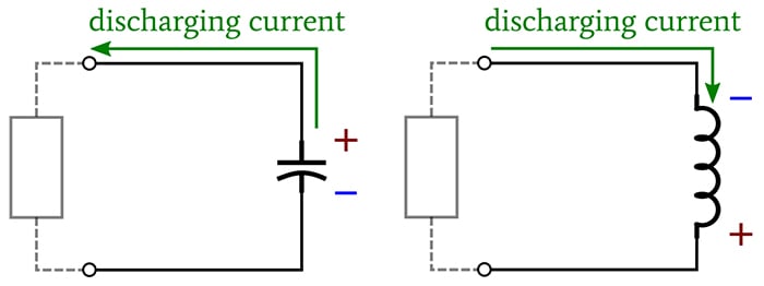
Depiction of how an inductor attempts to maintain current flow when it discharges.
What other questions do you have about voltage drops? Share your inquiries in the comments below.
Related Content


Would it be appropriate to emphasise that the driving force or EMF (measured in Volts) produced by the battery or source is achieved by, in the case of the battery, chemical reactions that effectively pile negative charges (electrons) on one plate by removing them from the other leaving behind a positive charge. When a load is connected the natural drive is for the electrons to travel around the circuit and get back to the positive plate to rebalance the situation. This drive is in fact the E.M.F. In flowing through the ‘load’ the electrons are depleted from the negative electrode but are replaced by the chemical reaction by electrons from the positive plate, and in doing so the current has to flow through the internal chemical constituents of the battery which also has a resistance to the flow. So the circuit shown above should have a source resistance showing, allowing one to estimate the new terminal voltage at the battery terminals which will now have fallen by an amount dependant on the source resistance. As the internal chemical constituents gradually degrade the internal resistance rises until the terminal voltage falls to such an extent that we consider the battery as flat.
While the expression “voltage drop” is commonly used when analyzing electronic circuits, it has led to much confusion to someone learning about circuits. It often leads to questions such as
“Why did the voltage drop?”
“What is the voltage drop at the base of the transistor?”
It would be best to avoid the use of the term “voltage drop” in introductory levels of electrical & electronics instruction.
The preferred expression is “potential difference”, such as, there is a potential difference between point-A and point-B. In other words, voltage does not drop. It doesn’t go away anywhere in the circuit. It is always there. It just depends on how and where you measure it.
Here is a hypothetical example. Connect a 0-ohm load across a 12V battery. What is the “voltage drop” across the load? Did it suddenly vanish to 0V?
Instead, we can experimentally measure the potential difference across the terminals of the battery and the terminals of the load. Then we can make theoretical assumptions about any surprises in observed measurements.