 Facebook
 Google
 GitHub
 Linkedin
Voltage Divider Calculator
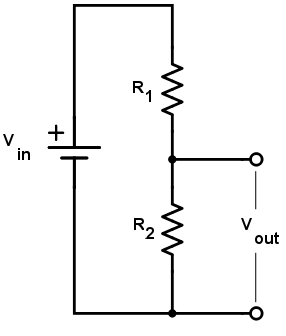
The voltage divider is a circuit used to create a voltage less than or equal to the input voltage.
Outputs
How to Find the Output Voltage of a Divider Circuit
The two resistor voltage divider is one of the most common and useful circuits used by engineers. The primary purpose of this circuit is to scale down the input voltage to a lower value based on the ratio of the two resistors. This calculator helps determine the output voltage of the divider circuit given the input (or source) voltage and the resistor values. Take note that the output voltage in actual circuits might be different, since resistor tolerance and load resistance (where the output voltage is connected) become factors.
Equation
$$V_{out} = V_{in}*\frac{R_{2}}{R_{1}+R_{2}}$$
Where:
$$V_{out}$$ = Output voltage. This is the scaled down voltage.
$$V_{in}$$ = Input voltage.
$$R_{1}$$ and $$R_{2}$$ = Resistor values. The ratio $$\frac{R_{2}}{R_{1}+R_{2}}$$ determines the scale factor.
Applications
Since voltage dividers are fairly common, they can be found in a number of applications. Below are just some of the places where this circuit is found.
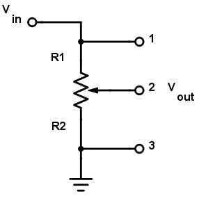
Potentiometers
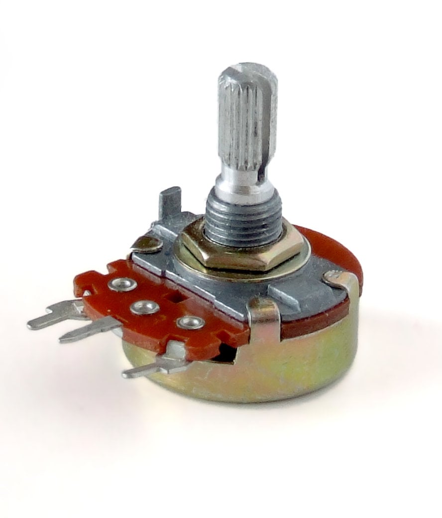
Perhaps the most common voltage divider circuit is the one involving a potentiometer, which is a variable resistor. A potentiometer's schematic diagram is shown below:
A "pot" usually has three external pins: two are the ends of the resistor and one is connected to the wiper arm. The wiper cuts the resistor in two and moves it, adjusting the ratio between the top half and the bottom half of the resistor. Connect the two external pins to a voltage (input) and a reference (ground) with the middle (wiper pin) as your output pin and you have yourself a voltage divider.
Level Shifters
Another area where voltage dividers are useful is when a voltage needs to be leveled down. The most common scenario is when interfacing signals between a sensor and a microcontroller with two different voltage levels. Most microcontrollers operate at 5V while some sensors can only accept a maximum voltage of 3.3V. Naturally, you want to level the voltage from the microcontroller down to avoid damage to the sensor. An example circuit is shown below:
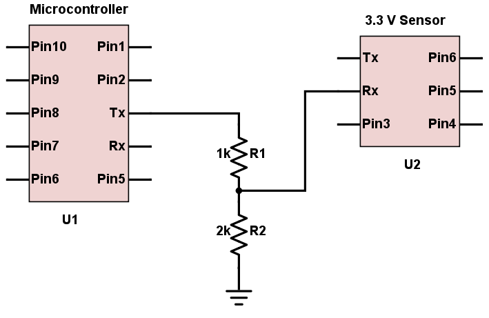
The circuit above shows a voltage divider circuit involving a 2kΩ and a 1kΩ resistor. If the voltage from the microcontroller is 5V, then the leveled-down voltage to the sensor is calculated as:
$$V_{out} = 5*\frac{2k\Omega}{2k\Omega+1k\Omega} = 3.33 V$$
This voltage level is now safe for the sensor to handle. Take note that this circuit only works for leveling down voltages and not leveling up.
Below are some other resistor combinations used for leveling down commonly encountered voltages:
| Resistor Combination | Use |
| 4.7 kΩ and 6.8 kΩ | 12V to 5V |
| 4.7 kΩ and 3.9 kΩ | 9V to 5V |
| 3.6 kΩ and 9.1 kΩ | 12V to 3.3V |
| 3.3 kΩ and 5.7 kΩ | 9V to 3.3V |
Resistive Sensor Reading
A lot of sensors are resistive devices and most microcontrollers read voltage, not resistance. Thus, a resistive sensor is usually connected in a voltage divider circuit with a resistor in order to interface with a microcontroller. An example setup is shown below:
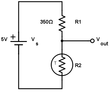
A thermistor is a sensor whose resistance changes proportionally to temperature. Let us say that the thermistor has a room temperature resistance of 350Ω. The paired resistance is chosen to also be 350Ω.
When the thermistor is at room temperature, the output voltage is:
$$V_{out} = 5*\frac{350\Omega}{350\Omega+350\Omega} = 2.5V $$
When the temperature increases, the thermistor resistance changes to 350.03Ω, the output changes to:
$$V_{out} = 5*\frac{350.03\Omega}{350\Omega+350.03\Omega} = 2.636V$$
Such a small change in voltage is detectable by a microcontroller. If the thermistor transfer function is known, the equivalent temperature can now be calculated.
Further Reading
Technical Article - Voltage and Current Dividers: What They Are and What They Do
Textbook - Chapter 6 - Divider Circuits And Kirchhoff's Laws
Related Content


Hi for some reason I am getting 0.02v ... Trying to get 5v from 12v! using 6.8k and 4.7k like it recommends… Strange. Definitely 12v before hand I checked.
hi peoples i have been building circuits for a few years , just wanted to say thanks for showing me a pot is a voltage divider , darn took long much thanks br