Facebook
 Google
 GitHub
 Linkedin
DC Lab - Potentiometer Voltage Divider
Project Overview
A potentiometer is an adjustable, variable resistor with three terminals. Two end terminals are connected to the ends of a resistive element, while a third central terminal is connected to an adjustable wiper that sets the resistive divider ratio. If a voltage is applied to the two ends, as illustrated in Figure 1, the central terminal output is an adjustable voltage.
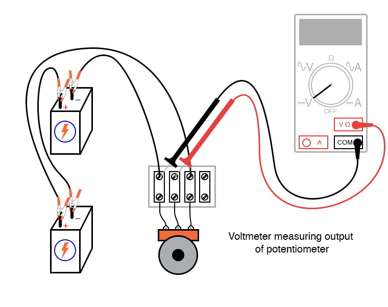
Figure 1. Using a potentiometer as a variable voltage divider.
Parts and Materials
- Two 6 V batteries or power supply
- Carbon pencil lead for a mechanical-style pencil
- Potentiometer, single turn, 5 kΩ to 50 kΩ, linear taper
- Potentiometer, multi-turn, 1 kΩ to 20 kΩ
Potentiometers are manufactured in panel-mount and breadboard-mount versions. Any potentiometer style will suffice for this experiment; however, we highly recommend a linear potentiometer for this experiment (and for most experiments in general). This is because a linear potentiometer exhibits a direct (linear) correlation between shaft position and voltage division ratio.
As a side note, keep in mind that If you salvage a potentiometer from an old radio or another audio device, you will likely get what is called an audio taper potentiometer. These potentiometers exhibit a logarithmic relationship between the division ratio and shaft position.
Learning Objectives
- How to connect and use potentiometers
- Understand voltage divider design and its function
- How to use a voltmeter
- How to use an ohmmeter
Instructions
Step 1: Begin this experiment with the pencil “lead” circuit of Figure 2 by applying a voltage across the graphite pencil lead.
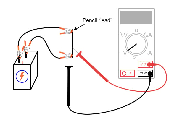
Figure 2. Observing the voltage divider function of a graphite pencil lead.
Pencils use a rod made of a graphite-clay mixture, not lead (the metal), to make black marks on paper. Graphite, being a mediocre electrical conductor, acts as a resistor connected across the battery by the two alligator-clip jumper wires.
Step 2: Connect the voltmeter like that shown in Figure 2, and touch the red test probe to the graphite rod. Move the red probe along the length of the rod and notice the voltmeter’s indication change. What probe position gives the greatest voltage value?
Let's take a look at Figure 3, which is the schematic diagram for the circuit of Figure 2.
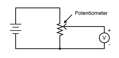
Figure 3. Schematic design illustrating a potentiometer symbol and how to measure the adjustable output voltage.
In Figure 3, the graphite rod pencil lead is a variable resistor, and the red probe from the voltmeter functions directly as the potentiometer wiper as you move it up and down the length of the rod. Essentially, the rod acts as a pair of resistors, with the ratio between the two resistances established by the position of the red test probe along the rod’s length. You can see an example of this in Figure 4.
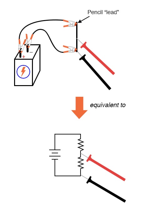
Figure 4. Two-resistor equivalent circuit for the pencil lead potentiometer.
Step 3: Next, change the voltmeter connection to the circuit to measure the voltage across the “upper resistor” of the pencil lead, as shown in Figure 5.
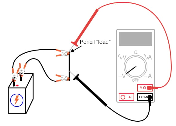
Figure 5. Measuring the voltage drop across the top portion of the graphite rod pencil lead.
Move the black test probe position along the length of the rod, noting the voltmeter indication. Which position gives the greatest voltage drop for the meter to measure? Does this differ from the previous arrangement? Why?
Step 4: Then, set up a circuit using a manufactured potentiometer, not the “home-made” one made from a pencil lead. Figures 6 and 7 provide examples of how this can be done with either terminal strips or a breadboard, respectively.
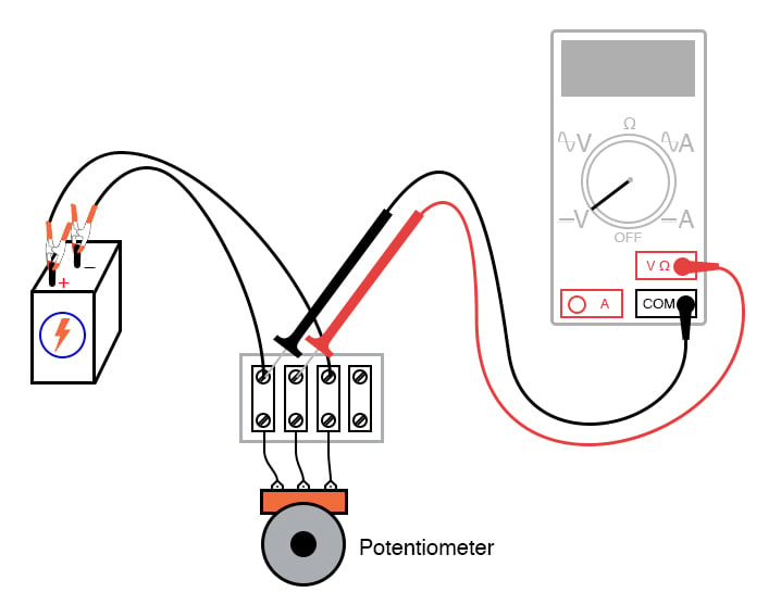
Figure 6. Connecting a potentiometer to a terminal strip and measuring the voltage output.
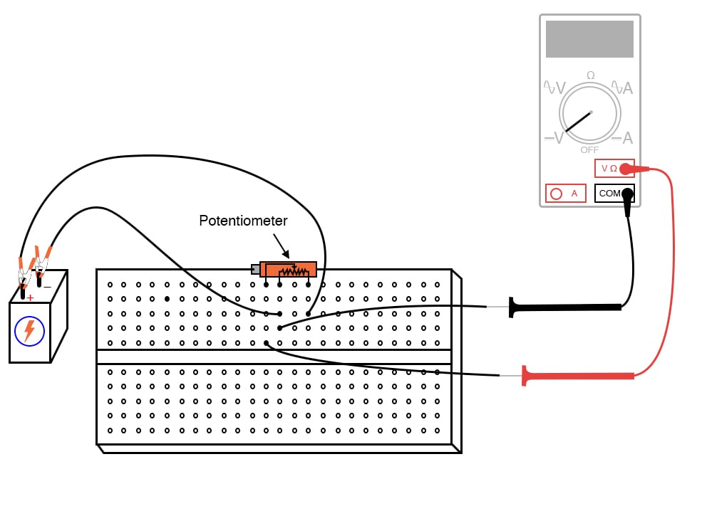
Figure 7. Connecting a potentiometer to a breadboard and measuring the voltage output.
Rotary and Linear Potentiometer Construction
Manufactured potentiometers enclose a resistive strip inside a metal or plastic housing and provide a mechanism for moving a wiper across the length of that resistive strip. Figure 8 is an illustration of a rotary potentiometer’s construction.
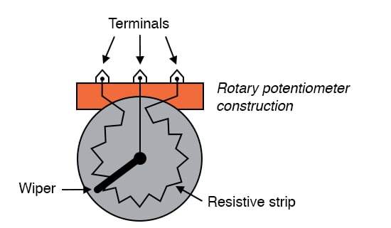
Figure 8. The construction of a rotary potentiometer.
Some rotary potentiometers have a spiral resistive strip and a wiper that moves axially as it rotates to require multiple shaft turns to drive the wiper from one end of the potentiometer’s range to the other. Multi-turn potentiometers are used in applications where the precise setting is important.
Linear potentiometers also contain a resistive strip, the only difference being the wiper’s direction of travel. Some linear potentiometers use a slide mechanism to move the wiper. Others use a screw mechanism to facilitate multiple-turn operation, as shown in Figure 9.
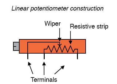
Figure 9. The construction of a screw-type linear potentiometer
It should be noted that not all linear potentiometers have the same pin assignments. On some, the middle pin is the wiper.
Next, for steps 5 through 10 of this experiment, you may use any form of potentiometer construction that is convenient.
Step 5: Measure the battery voltage while powering the potentiometer and record this voltage figure.
Step 6: Measure the voltage between the wiper and the potentiometer end connected to the negative (-) side of the battery.
Step 7: Adjust the potentiometer mechanism until the voltmeter registers exactly 1/3 of the total voltage. For a 6 V battery, this will be approximately 2 V.
Step 8: Now, connect two batteries in a series-aiding configuration to provide approximately 12 V across the potentiometer, as shown in Figure 10.
Figure 10. Connecting two batteries in series to double the applied voltage and measure the potentiometer output voltage.
Step 9: Measure the total battery voltage, and then measure the voltage between the same two points on the potentiometer (wiper and negative side).
Step 10: Divide the potentiometer’s measured output voltage by the measured total voltage. The quotient should be 1/3, the same voltage division ratio set in Step 8.
Related Content
Learn more about the fundamentals behind this project in the resources below.
Textbook:
Resistor Guide:
Worksheets:
- Potentiometers Worksheet
- Voltage Divider Circuits Worksheet
- Simultaneous Equations for Circuit Analysis Worksheet