Facebook
 Google
 GitHub
 Linkedin
DC Lab - Thermoelectricity
Project Overview
A thermocouple is made from two dissimilar conductors connected together at one end (Figure 1).
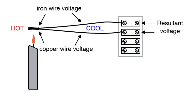
Figure 1. Applying heat to the thermocouple and measuring the voltage change.
A thermocouple is an application of the Seebeck effect: the production of a small voltage proportional to a temperature gradient along the length of a wire. This voltage is dependent upon the magnitude of the temperature difference and the type of wire.
Thermocouples are widely used as temperature-sensing devices because the mathematical relationship between temperature difference and resultant voltage is both repeatable and fairly linear. By measuring voltage, it is possible to infer temperature. Different temperature measurement ranges are possible by selecting different metal pairs to be joined together.
Please note that directly measuring the Seebeck voltage produced along a length of continuous wire from a temperature gradient is quite difficult and so will not be attempted in this experiment.
Parts and Materials
- Length of bare (uninsulated) copper wire
- Length of bare (uninsulated) iron wire. An iron wire may be obtained from a hardware store. If some cannot be found, an aluminum wire also works.
- Candle
- Ice cubes
Learning Objectives
- To illustrate thermocouple function and purpose
Instructions
Step 1: Twist one end of the iron wire together with one end of the copper wire, as illustrated on the left side of Figure 2.
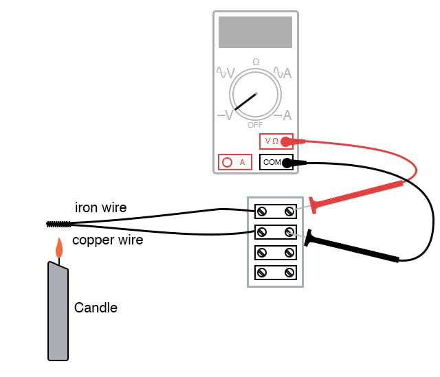
Figure 2. Measuring thermocouple voltage with a voltmeter.
Step 2: Connect the free ends of the iron and copper wires to respective terminals on a terminal strip.
Step 3: Set your voltmeter to its most sensitive range and connect it to the terminals where the wires attach, as shown in Figure 2. The meter should indicate nearly zero voltage.
What you have just constructed is a thermocouple: a device that generates a small voltage proportional to the temperature difference between the tip and the meter connection points. When the tip is at a temperature equal to the terminal strip, there will be no voltage produced, and thus no indication is seen on the voltmeter.
Step 4: Next, light a candle and insert the twisted-wire tip into the flame. You should notice an indication on your voltmeter. Note the sign of this voltage and the magnitude. Moving the wire nearer and further to the heat source to see how the voltage changes.
Thermocouples, being made of two dissimilar metals joined at one end, produce a voltage proportional to the temperature of the junction. The temperature gradient along both wires resulting from a constant temperature at the junction produces different Seebeck voltages along those wires’ lengths because the wires are made of different metals. The resultant voltage between the two free wire ends is the difference between the two Seebeck voltages.
Step 5: Remove the thermocouple tip from the flame and let it cool until the voltmeter indication is nearly zero again.
Step 6: Next, touch the thermocouple tip to an ice cube and note the voltage indicated by the meter. Is it a greater or lesser magnitude than the result obtained with the flame? How does the polarity of this voltage compare with that generated by the flame?
Step 7: After touching the thermocouple tip to the ice cube, warm it by holding it between your fingers. It may take a short while to reach body temperature, so be patient while observing the voltmeter’s indication.
Related Content
Learn more about the fundamentals behind this project in the resources below.
Textbook:
Technical Articles:
- Thermocouple Principles—the Seebeck Effect and Seebeck Coefficient
- Thermocouple Basics—Using the Seebeck Effect for Temperature Measurement
- What is Cold Junction Compensation in Thermocouples?
- Thermocouple Signal Conditioners and Signal Conditioning Near the Cold Junction