Facebook
 Google
 GitHub
 Linkedin
Constructing a Solar-Powered Snake Robot
Learn how to create a batteryless crawling robot using basic electronic components and a 3D-printed chassis.
In today's project article, we'll create a 3D-printed, solar-powered snake robot without the use of any microcontrollers. Instead of computer programming, its movements are determined by simple sensory inputs. When exposed to the sun or a powerful enough incandescent lightbulb, it crawls forward in a straight line.
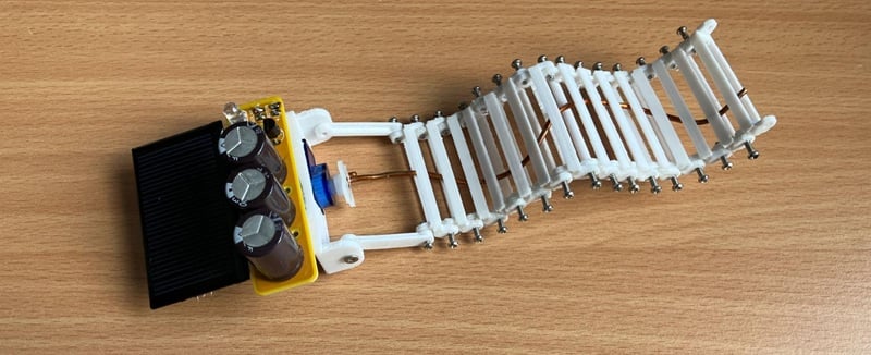
Figure 1. The completed snake robot. Image used courtesy of Kristijan Nelkovski
This project is based on the principles of BEAM robotics, as well as on some research into wave-like mechanical mobility inspired by snakes. Before we jump into building our robot, let's talk about these influences.
BEAM Robotics
Originally invented by Mark W. Tilden, BEAM robots are self-powered and don't contain any microprocessors or microcontrollers. Instead, they use only simple analog electronics. The goal is for the robot to react more like a biological organism than a complex and sequential computer algorithm.
BEAM stands for Biology, Electronics, Aesthetics, and Mechanics. As the 'Aesthetics' portion of the acronym suggests, robots in this category are designed to look like living beings, not just behave like them. Figure 2 shows Mark Tilden and some of the proof-of-concept BEAM robots he created.
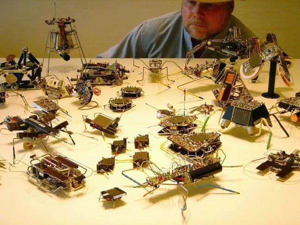
Figure 2. Mark Tilden with various proof-of-concept BEAM robots. Image used courtesy of Medium and Mark W. Tilden
In addition to the above principles, BEAM robots typically follow a few simple design rules. These include:
- Achieving stimulus-response using the lowest number of components possible.
- Using renewable energy to power part or all of the system.
- Constructing circuits from recycled components.
The SAW Robot
The body shape and locomotion mechanism of our robot stem from research published back in 2016 by Dr. David Zarrouk and his students at Ben Gurion University. The robot they developed, called the Single Actuator Wave-like Robot or SAW Robot, is shown in Figure 3.
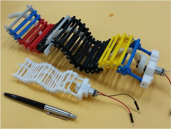
Figure 3. Original SAW robot. Image used courtesy of Ben-Gurion University of the Negev
The SAW robot produces a perpendicular snake-like motion using a single DC motor. Its spine is made up of thin, hollow, rectangular brackets daisy-chained together using two machine screws. A single, long helix is threaded through the robot in between the openings of each bracket, forcing the whole construction into a sinusoidal shape.
This helical component is fastened to the shaft of the motor, but not the brackets themselves, allowing it to freely move around their openings. When power is applied to the motor, the rotational motion of the helix produces an advancing sine wave with a large amplitude. This propels the robot either forward or backward.
Building the Snake Robot
Like most of my projects, you could get away with building this one on a breadboard, perfboard, or even by soldering each component point-to-point (which is how many BEAM robots are actually designed). I have, of course, created a small PCB design. You can download it here:
The rest of the project files are available here:
Table 1 is the official BOM for this project. Most, if not all, of these components can be found lying around the average electronics workshop. You could also take a true BEAM recycling and reusing approach and source them from disused or broken electronics.
Table 1. Bill of materials.
| Part | Quantity | Notes |
| 2N3906 | 1 | Alternatives: BC327, PN2907, or similar PNP transistor. |
| 2N3904 | 1 | Alternatives: BC337, PN2222, or similar NPN transistor. |
| 2.2 kΩ resistor | 1 | Any resistor between 1 kΩ and 10 kΩ would work. |
| 4700 µF capacitor | 3+ | Any capacitors above 470 µF would work. |
| FLED | 1 | A zener diode or multiple regular diodes connected in series also work. |
| Solar cell | 1 | Must be able to output at least 3 V. |
| Servo motor | 1 | Various 9 gram micro servos would also work. |
| 3D-printed motor mount | 1 | To hold the motor, circuit, and solar cell together. |
| 3D-printed connector | 2 | To connect the motor mount to the robot's brackets. |
| 3D-printed bracket | 15+ | Locomotion elements of the robot. |
| 1.5 mm machine screw | 34+ | Twice the number of brackets and connectors. |
| Stiff piece of wire | 1 | To create the central helical structure of the robot. |
You can use any type of micro servo. However, you will have to gut its internal electronics and connect the actual DC motor terminals directly to our circuit. This is because we're using the servo for its housing, which has an easy-to-work-with rectangular geometry and screw points, and for the high torque of its gearbox. We're not using the servo's driver mechanism or feedback circuitry, which you would in any case need a microcontroller to properly utilize.
If you decide to reuse old electronic components, note that your most likely weak links are the electrolytic capacitors. If you've ever fixed up old electronics, more often than not, an otherwise perfectly functioning system won't power up because it has a failed electrolytic capacitor shorting its circuit. It's important that you check old capacitors for any potential damage.
Next, let's discuss how we'll power our snake robot.
The Solar Engine Circuit
Under direct sunlight, a small solar panel provides around 5 V and probably less than 100 mA. This is just a fraction of the power that even a couple of AA batteries would be able to provide a micro DC motor, and it's certainly not enough for our robotics project.
Fortunately, we can construct what is known as a solar engine circuit. This system allows us to store a solar cell's trickle of power and release it later as a usable burst of energy, intermittently propelling the snake robot forward.
The majority of solar engine designs monitor voltage collected in one or more capacitors in order to decide when there is enough power to direct it towards an actuator. This type of circuit is simple to build and leaves most of its stored energy for actually driving a motor.
For this project, I chose a variant of Tilden's diode solar engine design. The schematic for the diode solar engine circuit is shown in Figure 4.
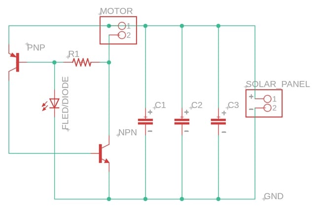
Figure 4. Diode solar engine circuit diagram. Image used courtesy of Kristijan Nelkovski
Under direct sunlight, voltage across our circuit's capacitors slowly rises. When it exceeds the diode's threshold voltage, it starts to conduct electricity. At this point, the PNP transistor connected with the diode at its base turns on, applying current to the base of the NPN transistor. This closes the circuit between our motor and the capacitors, thus powering the robot on.
As the NPN collector voltage drops to zero, current through the resistor reverses and activates the PNP transistor, effectively taking the diode out of the circuit. Our robot then runs until the voltage of the capacitor drops and the whole process repeats again.
Chassis and Spine Design
Although you can get away with not having a PCB, you won't be able to achieve snake-like locomotion without 3D-printing the robot's chassis. Searching online, I wasn't able to find the original CAD files for Dr. Zarrouk's robot. However, I did find some alternatives.
My design is heavily based on Noobnood's version from thingiverse, albeit with some modifications. For one thing, I modified each bracket to be printable as a single component without having to glue parts together. I also made one universal holder for the motor, PCB, and solar panel. Figure 5 shows how the holder attaches to the spine brackets.
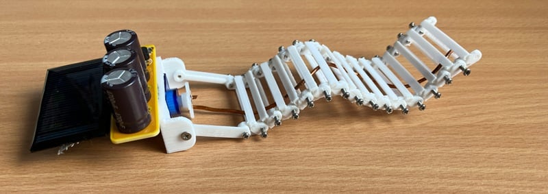
Figure 5. Side view of the solar-powered snake robot. Image used courtesy of Kristijan Nelkovski
As you can see above, the snake robot I built has 15 spine brackets. You can use more brackets if you want to make the snake longer—I just had a limited number of 1.5 mm machine screws available.
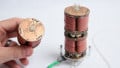
For the central helix, I used a single piece of copper wire coiled and stretched out in a helicoidal shape (copying Noobnood's plastic one). 3D printing would have taken way too long, and had the potential to cause lots of headaches. Plastic can break easily at such a small scale, and that would have meant I had to print the helix all over again.
The wire is bent at the tip and attached to one of the motor's servo horns. I didn't use any specific wire gauge, and I also eyeballed the actual helix dimensions.
Your Turn
Once you've built the solar engine circuit and its locomotion system, watch your snake bot spring into action as soon as the sun's rays hit its solar panel! You can see my prototype in motion by clicking on the video link in Figure 6.
Figure 6. The snake robot in motion. Video used courtesy of Kristijan Nelkovski
Now you know how to build a simple solar engine and utilize it as the "brains" of a robot without the need to write any computer code. What other type of project would you use this circuit for? Share your ideas in the comments below!
Snake graphics in featured image used courtesy of Canva