 Facebook
 Google
 GitHub
 Linkedin
What is Cold Junction Compensation in Thermocouples?
Learn about the theory behind cold junction compensation in thermocouples using the Seebeck voltage, reference tables, and by finding the hot junction temperature.
The setup used to specify the response of a thermocouple is different from the practical arrangement used when dealing with thermocouples. Thermocouple look-up tables and models are referenced to 0 °C, which is not the case in practical thermocouple applications. The procedure, known as cold junction compensation, should be followed to successfully interpret the thermocouple output.
In this article, we’ll look at the theory behind cold junction compensation and see how this procedure should be used in practice.
Thermoelectric-based Thermometry—Measuring Thermocouple Output
In a previous article, we learned that thermocouples are constructed of two dissimilar metals that are joined together at one end as shown below in Figure 1.
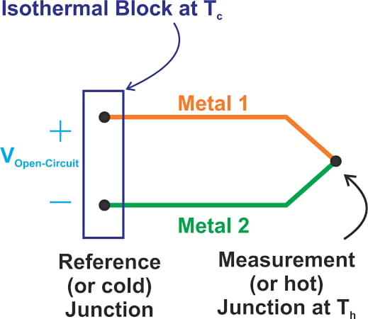
Figure 1. A thermocouple constructed of two dissimilar metals.
Figure 2 shows a simplified diagram for measuring the thermocouple output voltage (VOpen-Circuit).
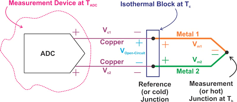
Figure 2. A simplified diagram for measuring the thermocouple output.
In this example, an isothermal block is used where the thermocouple wires connect to the copper conductors. The isothermal block is at a temperature of Tc. The ADC (analog-to-digital converter) is at a different temperature (TADC). Thus, we expect some Seebeck voltage to develop across the copper traces. Since both of the copper traces experience the same temperature gradient, the same Seebeck voltage will appear across the two copper traces (Vc1 = Vc2).
A KVL (Kirchhoff's voltage law) equation reveals that the ADC measures only the Seebeck voltage produced by the thermocouple wires VOpen-Circuit (assuming that the ADC input current is negligible). The thermocouple voltage, shown in Equation 1, is given by:
$$V_{Open-Circuit}=V_{m1}-V_{m2}=S_{m1}\times(T_{h}-T_{c})-S_{m2}\times(T_{h}-T_{c})$$
Equation 1.
Where Th is the hot junction temperature and Sm1 and Sm2 denote the Seebeck coefficient of metal 1 (m1) and metal 2 (m2), respectively. Factoring out the common terms, we get Equation 2 below:
$$V_{Open-Circuit}=(S_{m1}-S_{m2})\times(T_{h}-T_{c})$$
Equation 2.
Before moving ahead, I’d like to emphasize that Equation 1 is based on the assumption that the Seebeck coefficient of the thermocouple material doesn’t change with temperature. If we take the temperature dependence into account, we need to use an integral expression to find the voltage across each metal segment. For example, the voltage across metal 1 would be:
$$V_{m1}=\int\limits^{T_{h}}_{T_{c}}S_{m1}(T)dT$$
This integral equation simplifies to \(V_{m1} = S_{m1}\times (T_{h}-T_{c})\) if the Seebeck coefficient doesn’t change with temperature. We know that the Seebeck coefficient is actually temperature-dependent. However, since our intention here is just to show how the thermocouple output is used to measure temperature, we’ll use the simpler form of the equations rather than the integral version.
Cold Junction Temperature Requirements
From Equation 2, we observe that the voltage produced by a thermocouple is proportional to the temperature difference between the hot and cold junctions. To determine the absolute temperature of the hot junction (Th), we need to know the temperature of the cold junction (Tc). Therefore, an additional temperature sensor, such as a thermistor, RTD (resistance temperature detector), diode, or IC-based sensor, is required to measure the cold junction temperature.
This requirement is typically not a big challenge; however, one might ask: If we have this additional sensor in our system, why don’t we use it to measure the hot junction temperature? The answer is a no-brainer: thermocouples are rugged and support a wide temperature range. Sensors that are used to measure the cold junction temperature cannot be used in corrosive environments or high-temperature applications for which thermocouples are perfectly suited.
Thermocouple Response Using Seebeck Voltage and a Thermocouple Reference Table
In addition to knowing the reference junction temperature, we need to know the thermocouple response to determine the temperature to be measured. The “standards community” and thermocouple manufacturers usually specify the output of a thermocouple relative to a reference junction at 0 °C. The measurement setup is shown in Figure 3.
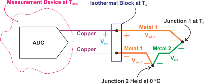
Figure 3. Measurement setup for a thermocouple.
While junction 2 is held at 0 °C, the temperature of junction 1 is swept through the temperature range of interest. The output, Vout, for each temperature is recorded and provided as a table or a mathematical equation. An excerpt from the T-type thermocouple reference table covering the temperature range from 0 °C to 50 °C is shown below (Table 1).
Table 1. Data used courtesy of REOTEMP.
| °C | 0 | 1 | 2 | 3 | 4 | 5 | 6 | 7 | 8 | 9 | 10 |
| Thermoelectric Voltage in mV | |||||||||||
| 0 | 0.000 | 0.039 | 0.078 | 0.117 | 0.156 | 0.195 | 0.234 | 0.273 | 0.312 | 0.352 | 0.391 |
| 10 | 0.391 | 0.431 | 0.470 | 0.510 | 0.549 | 0.589 | 0.629 | 0.669 | 0.709 | 0.749 | 0.790 |
| 20 | 0.790 | 0.830 | 0.870 | 0.911 | 0.951 | 0.992 | 1.033 | 1.074 | 1.114 | 1.155 | 1.196 |
| 30 | 1.196 | 1.238 | 1.279 | 1.320 | 1.362 | 1.403 | 1.445 | 1.486 | 1.528 | 1.570 | 1.612 |
| 40 | 1.612 | 1.654 | 1.696 | 1.738 | 1.780 | 1.823 | 1.865 | 1.908 | 1.950 | 1.993 | 2.036 |
As an example, the above table indicates that a T-type thermocouple with a reference junction at 0 °C produces 1.993 mV for Th = 49 °C. With that in mind, how can we use a standard thermocouple reference table to determine the hot junction temperature in a typical arrangement such as that depicted in Figure 2? Generally, thermocouple reference tables are obtained from the setup depicted in Figure 3. This setup uses a reference junction at 0 °C and doesn’t look like the one shown in Figure 2.
Let’s examine the topology shown in Figure 3 a bit more closely. Writing the Seebeck voltage equations for this circuit, we obtain:
$$V_{out}=V_{m1,1}\,+\,V_{m2}\,+\,{V_{m1,2}}=S_{m1}\times(T_{h}-T_{c})+S_{m2}\times(T_{ref}-T_{h})+S_{m1}\times(T_{c}-T_{ref})$$
With the reference junction at 0 °C (Tref = 0), the above equation simplifies to:
$$V_{out}=(S_{m1}-S_{m2})\times T_{h}$$
Equation 3.
A thermocouple reference table, which gives Vout for a given Th, actually specifies the value of Sm1 – Sm2 at different temperatures. Now, comparing Equation 3 with Equation 2, we can observe that VOpen-Circuit in Figure 2 can be written as the sum of two terms similar to the right side of Equation 3:
$$V_{Open-Circuit}=(S_{m1}-S_{m2})\times T_{h}-(S_{m1}-S_{m2})\times T_{c}$$
Equation 4.
The terms \((S_{m1}-S_{m2})\times T_{h}\) and \((S_{m1}-S_{m2})\times T_{c}\) are the values we obtain from a reference table for temperatures Th and Tc. Therefore, having the reference table, we can relate the three parameters VOpen-Circuit, Tc, and Th to each other. Put differently, the voltage produced by a thermocouple, VOpen-Circuit, equals the reference table value at Th minus the table value at Tc.
Measuring Hot Junction Temperature Using a Practical Thermocouple
Let’s consider an example to further clarify the above discussion. Assume that the open-circuit voltage measured from a T-type thermocouple is VOpen-Circuit = 0.788 mV and the cold junction temperature is Tc = 25 °C. What is the hot junction temperature?
From Equation 4, we know that VOpen-Circuit can be written as:
$$V_{Open-Circuit}=Table\,\,Value\,\,at\,\,T_{h}-\,Table\,\,Value\,\,at\,\,T_{c}$$
From Table 1, we observe that a T-type thermocouple produces 0.992 mV at Tc = 25 °C. Substituting our data in the above equation, we have:
$$0.788\,mV=Table\,\,Value\,\,at\,\,T_{h}-0.992\,mV$$
This simplifies to:
$$Table\,\,Value\,\,at\,\,T_{h}=1.78\,mV$$
Again from the thermocouple reference table (Table 1), we observe that this voltage corresponds to a temperature of Th = 44 °C.
Summarizing the Cold Junction Compensation Calculation
The above procedure that allows us to interpret the output of a practical thermocouple is known as cold junction compensation. Cold junction compensation can be summarized as:
- Measure the thermocouple output voltage (VOpen-Circuit)
- Measure the cold junction temperature (Tc)
- Use the thermocouple reference table to find the voltage (Vc) corresponding to the cold junction temperature (Tc).
- Add Vc to VOpen-Circuit
- Use the thermocouple reference table to find the temperature corresponding to Vc + VOpen-Circuit. This temperature is the hot junction temperature (Th).
To see a complete list of my articles, please visit this page.


this article help me understand how to practically test a temperature with thermocouple, thank you!