 Facebook
 Google
 GitHub
 Linkedin
Introduction to Temperature Sensors: Thermistors, Thermocouples, RTDs, and Thermometer ICs
Learn about different temperature sensors, namely: thermistors, thermocouples, RTDs (resistive temperature detectors), analog thermometer ICs and digital thermometer ICs.
Learn about various types of temperature sensors and each of their advantages and disadvantages.
Temperature Sensor Types
Temperature sensors are among the most commonly used sensors. All types of equipment use temperature sensors, including computers, cars, kitchen appliances, air conditioners, and (of course) home thermostats. The five most common types of temperature sensors include:
- Thermistor
- Thermocouple
- RTDs
- Analog thermometer ICs
- Digital thermometer ICs
This article will give you a succinct intro to each of the sensor types listed.
Thermistor Basics—NTC vs PTC Thermistor
As the name implies, the thermistor (i.e., thermal resistor) is a temperature-sensing device whose resistance is a function of its temperature.
Thermistors are available in two types: PTC (positive temperature coefficient) and NTC (negative temperature coefficient). The resistance of a PTC thermistor increases as the temperature increases. In contrast, the resistance of an NTC thermistor decreases as temperature increases, and this type seems to be the most commonly used thermistor. See Figure 1 below.
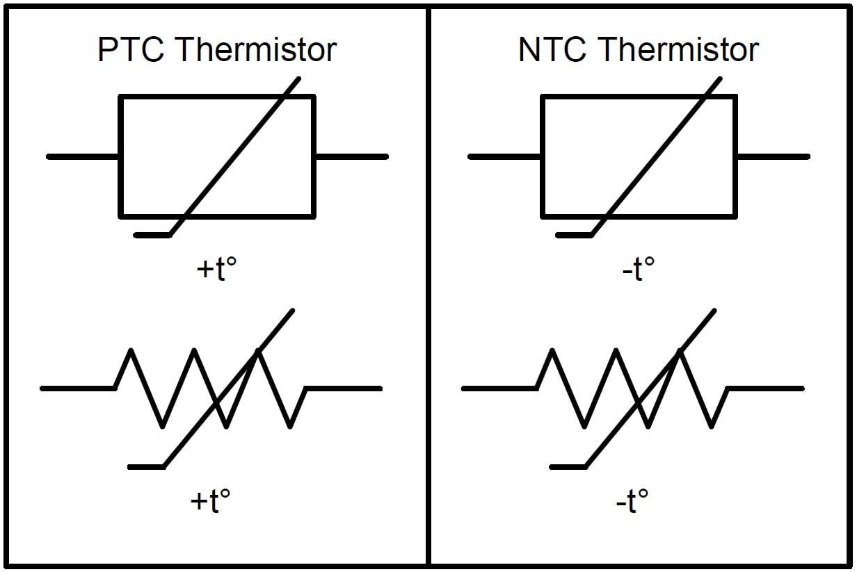
Figure 1. PTC (left) and NTC (right) thermistor electrical symbols.
It's important to realize that the relationship between a thermistor's resistance and its temperature is very non-linear, as seen in Figure 2.
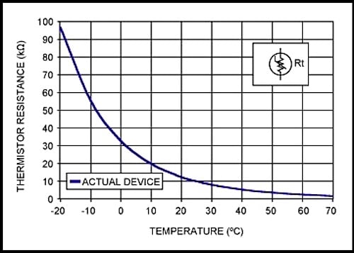
Figure 2. An NTC thermistor resistance vs. temperature. Image used courtesy of Maxim Integrated
NTC Thermistor Resistance Equation
The standard equation for an NTC thermistor's resistance as a function of temperature is given by:
$$R_T=R_{25C}\cdot e^{\left\{\beta\left[\left(1/\left(T+273\right)\right)-\left(1/298\right)\right]\right\}}$$
Where:
-
R25C is the thermistor's nominal resistance at room temperature (25 °C). This value is normally provided in the datasheet.
-
β (beta) is the thermistor's material constant in Kelvin. This value is normally provided in the datasheet.
-
T is the thermistor's actual temperature in Celsius.
However, there are two easy techniques used to linearize a thermistor's behavior, namely, resistive mode and voltage mode.
Resistive Mode Linearization
Resistive mode linearization places a normal resistor in parallel with the thermistor. If the value of the resistor is the same as that of the thermistor at room temperature, the linearization region will be symmetrical around room temperature. See Figure 3 below.
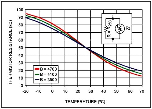
Figure 3. Resistive mode linearization. Image courtesy of Maxim Integrated
Voltage Mode Linearization
Voltage mode linearization, on the other hand, places the thermistor in series with a normal resistor forming a voltage divider circuit—the voltage divider circuit must be connected to a known, fixed, and stable voltage reference, VREF.
This configuration has the effect of producing an output voltage that is somewhat linear over temperature. Like resistive mode linearization, if the resistor's value is equal to the thermistor's resistance at room temperature, then the linearization region will be symmetrical around room temperature (Figure 4).
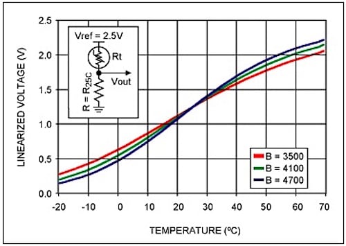
Figure 4. Voltage mode linearization. Image courtesy of Maxim Integrated
Thermocouples—How Does a Thermocouple Work?
Thermocouples are commonly used for measuring higher temperatures and larger temperature ranges.
To summarize how thermocouples work, any conductor subjected to a thermal gradient will generate a small voltage. This phenomenon is known as the Seebeck effect. The magnitude of the generated voltage is dependent upon the type of metal. Practical applications of the Seebeck effect involve two dissimilar metals that are joined at one end and separated at the other end. The junction's temperature can be determined via the voltage between the wires at the non-junction end.
Thermocouple Types
There are various types of thermocouples. Certain combinations of alloys have become popular, and the desired combination is driven by variables including cost, availability, chemical properties, and stability. Different types are best suited for different applications, and they are commonly chosen based on the required temperature range and sensitivity.
Figure 5 shows a graph of thermocouple characteristics.
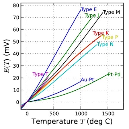
Figure 5. Thermocouple characteristics. Image courtesy of Wikipedia.
Resistive Temperature Detectors (RTDs)
Resistive temperature detectors, also known as resistance thermometers, are perhaps the simplest temperature sensor to understand. RTDs are similar to thermistors in that their resistance changes with temperature. However, rather than using a special material that is sensitive to temperature changes—as with a thermistor—RTDs use a coil of wire wrapped around a core made from ceramic or glass.
The RTD wire is of pure material, typically platinum, nickel, or copper, and the material has an accurate resistance–temperature relationship that is used to determine the measured temperature.
Analog Thermometer ICs
Instead of using a thermistor and a fixed-value resistor in a voltage divider circuit, an alternative solution would be an analog low-voltage temperature sensor, such as the TMP36 from Analog Devices. In contrast to a thermistor, this analog IC provides an almost linear output voltage; the slope is 10 mV/°C over a temperature range of -40 to +125 °C, and it’s accurate to ±2 °C. See Figure 6 below.
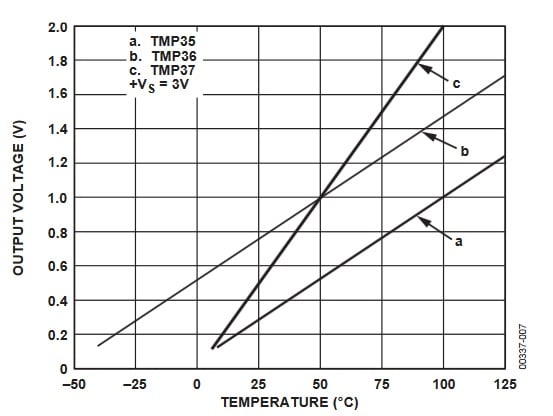
Figure 6. A plot from the TMP36 datasheet.
Although these devices are extremely easy to use, they are considerably more expensive than a thermistor-plus-resistor combination.
Digital Thermometer ICs
Digital temperature devices are more complex, but they can be highly accurate. Also, they can simplify your overall design because analog-to-digital conversion takes place inside the thermometer IC instead of a separate device such as a microcontroller. For example, the DS18B20 from Maxim Integrated has an accuracy of ±0.5 °C and a temperature range of -55 °C to +125 °C.
Also, some digital ICs can be configured to harvest energy from their data line, allowing them to be connected using just two wires (i.e., data/power and ground). Click here for more information on this “1-wire” interface.
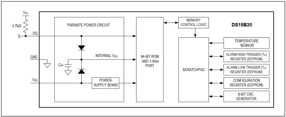
Figure 7. DS18B20 block diagram, taken from the DS18B20 datasheet. Click to enlarge.
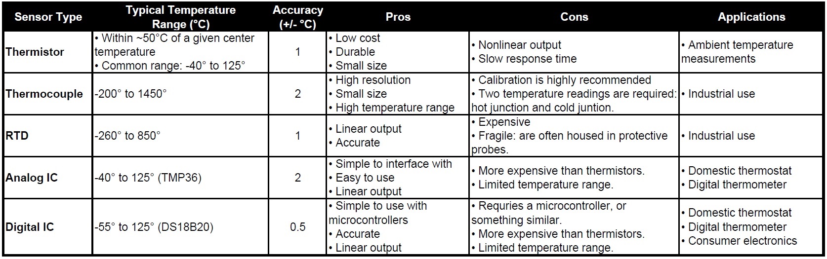
Comparing Types of Temperature Sensors
Table 1 below shows a comparison between the different temperature sensors discussed. However, remember that this information should be received as a generalization. The table is intended primarily for those who lack extensive experience with and/or knowledge of temperature sensors.
Table 1. A brief comparison of the temperature sensors which were discussed.
Featured image used courtesy of W11 Stop
Related Content


While the NTC thermistor is highly non-linear, the PTC thermistor is fairly linear. The PTC thermistor is not common for temperature measurement but is VERY COMMON when used as a self-resettable fuse.
Another common temperature sensor is the silicon diode. It has a very linear temperature coefficient over the normal operating range a semiconductor is used in, typically 0 to 50 C. This range can be stretched some if needed. The tempco is typically -2.2mV/degree C, but can vary some with the exact device used.
Thermistors are very popular for temperature measurement, specially for digital termometers and loggers with internal sensors used for ambient temperature measurement.