Facebook
 Google
 GitHub
 Linkedin
DC Lab - Rheostat Range Limiting
Project Overview
This experiment explores the different resistance ranges obtainable from combining fixed-value resistors with a potentiometer connected as a rheostat. Creating a custom resistance range from fixed-value resistors and a potentiometer (as illustrated in Figure 1) is useful for producing precise resistances required for certain circuits, especially meter circuits.
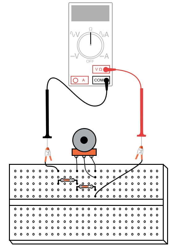
Figure 1. A variable resistance rheostat with zero-calibration and range set using fixed resistors in series and parallel.
In many electrical instruments—multimeters especially—resistance is the determining factor for the instrument’s range of measurement. In addition, if an instrument’s internal resistance values are not precise, neither will its indications. The rheostat allows the tuning of resistance to a precise value.
Parts and Materials
- Several 10 kΩ resistors
- One 10 kΩ potentiometer, linear taper
Learning Objectives
- Learn about the zero-calibration
- Learn about the span of a variable resistance range
- Create a custom resistance range from fixed-value resistors and a potentiometer
- To show calibration theory and practice
Instructions
Step 1: To begin, connect a 10 kΩ potentiometer as a rheostat with no other resistors connected, as shown in Figure 2.
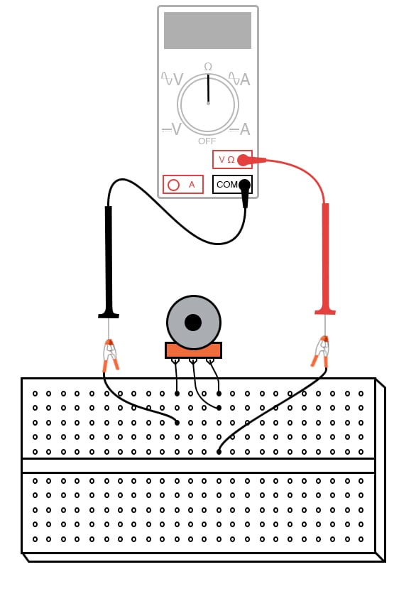
Figure 2. Connect the potentiometer as a variable resistance rheostat.
Step 2: Adjusting the potentiometer through its full range of travel should result in a resistance that varies smoothly from 0 Ω to 10,000 Ω by measuring with an ohmmeter, as illustrated above in Figure 2.
Shifting the Variable Resistance Range Using Zero-calibration
Step 3: Suppose we wanted to elevate the lower end of this resistance range so that we had an adjustable range from 10 kΩ to 20 kΩ with a full sweep of the potentiometer’s adjustment. This could be easily accomplished by adding a 10 kΩ resistor in series with the potentiometer. Add a 10 kΩ resistor to the circuit, as shown in Figure 3, and re-measure total resistance while adjusting the potentiometer. A shift in the low end of an adjustment range is called a zero-calibration in metrological terms. With the addition of a series 10 kΩ resistor, the “zero point” was shifted upward by 10,000 Ω.
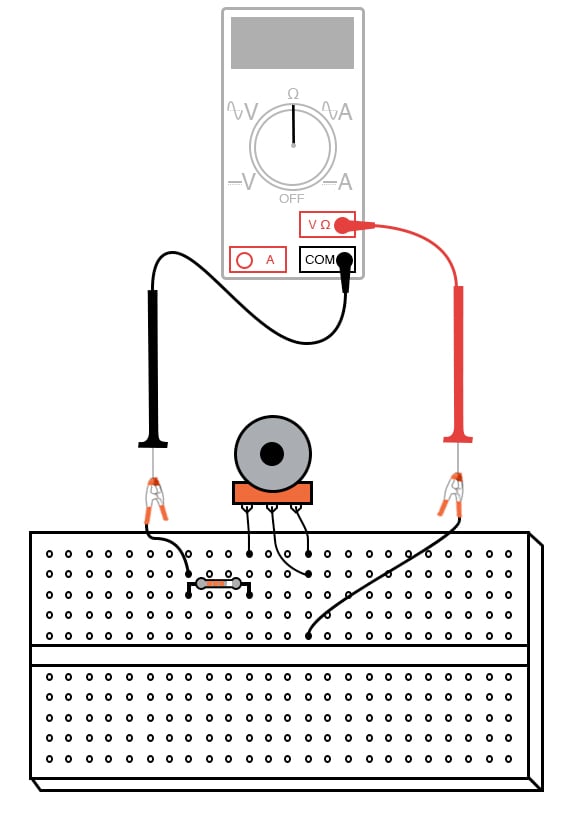
Figure 3. Add a resistor in series with the rheostat to shift the variable resistance range.
Adjusting the Span of the Variable Resistance Range
The difference between the high and low ends of the adjustable range—called the span of the circuit—has not changed, though. A range of 10 kΩ to 20 kΩ has the same 10,000 Ω span as a range of 0 Ω to 10 kΩ. If we wish to shift the span of this rheostat circuit as well, we must change the range of the potentiometer itself. We could replace the potentiometer with one of another value. We could also simulate a lower-value potentiometer by placing a resistor in parallel with it, diminishing its maximum obtainable resistance. This will decrease the span of the circuit from 10 kΩ to something less.
Step 4: Add a 10 kΩ resistor in parallel with the potentiometer, as shown in Figure 4. This will reduce the span to one-half of its former value: from 10 KΩ to 5 kΩ. Now the calibrated resistance range of this circuit will be 10 kΩ to 15 kΩ:
Figure 4. Add a resistor parallel to the rheostat to reduce the variable resistance range.
There is nothing we can do to increase the span of this rheostat circuit short of replacing the potentiometer with another of greater total resistance. Adding resistors in parallel can only decrease the span. However, there is no such restriction with calibrating the zero point of this circuit, as it began at 0 Ω and may be made as great as we wish by adding resistance in series.
Step 5: A multitude of resistance ranges may be obtained using only 10 KΩ fixed-value resistors if we are creative with series-parallel combinations of them. For instance, we can create a range of 7.5 kΩ to 10 kΩ by building the following circuit in Figure 5.
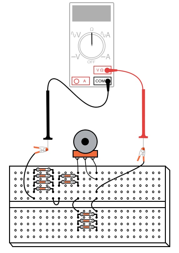
Figure 5. Using series and parallel resistor combinations of only 10 kΩ to adjust the rheostat range and span.
This same circuit is represented as a schematic diagram in Figure 6.
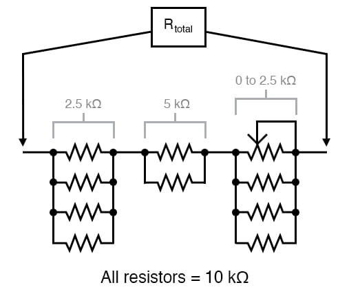
Figure 6. Schematic representation of the series-parallel combination of 10 kΩ resistors illustrated in Figure 4.
From here, you can experiment with different resistor “networks” and note the effects on the total resistance range.
Finding a fixed-value resistor of just the right resistance for placement in an instrument circuit design is unlikely, so custom resistance “networks” may need to be built to provide the desired resistance. Having a potentiometer as part of the resistor network provides a means of correction if the network’s resistance should drift from its original value. Designing the network for a minimum span ensures that the potentiometer’s effect will be small so that precise adjustment is possible and so that accidental movement of its mechanism will not result in severe calibration errors.
Related Content
Learn more about the fundamentals behind this project in the resources below.
Calculators:
Textbook:
Resistor Guide:
Worksheets:
- Potentiometers Worksheet
- Parallel DC Circuits Worksheet
- Series-parallel DC Circuits Worksheet
- Series DC Circuits Worksheet
Video Tutorials and Lectures: