Facebook
 Google
 GitHub
 Linkedin
DC Lab - Voltage Divider
Project Overview
In this project, you will build a voltage divider circuit and measure the voltages and currents using a voltmeter and an ammeter. We will demonstrate how you can build the voltage divider circuit using three different methods:
- On a breadboard (as shown in Figure 1)
- On a terminal strip
- Free-form using alligator-style clips
The goal is to familiarize yourself with the different techniques and their advantages and disadvantages.
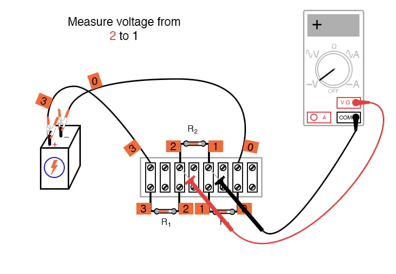
Figure 1. Building a voltage divider circuit and measuring the voltages.
Parts and Materials
- 6 V battery or DC power supply
- Assortment of at least three resistors between 1 kΩ and 100 kΩ in value
Note: I’m purposely restricting the resistance values between 1 kΩ and 100 kΩ for the sake of obtaining accurate voltage and current readings with the meter. With very low resistance values, the internal resistance of the ammeter has a significant impact on measurement accuracy. Very high resistance values may cause problems for voltage measurement, the internal resistance of the voltmeter substantially changing circuit resistance when it is connected in parallel with a high-value resistor.
Learning Objectives
- Voltmeter use
- Ammeter use
- Ohmmeter use
- Use of Ohm’s law
- Use of Kirchhoff’s voltage law (KVL)
- Voltage divider design
Instructions
Step 1: Select three resistors from your resistor assortment and measure the resistance of each one with an ohmmeter. Record these resistance values for reference in your circuit calculations.
Step 2: Next, connect the three resistors in series with the 6 V battery, as shown in the circuit schematic of Figure 2.
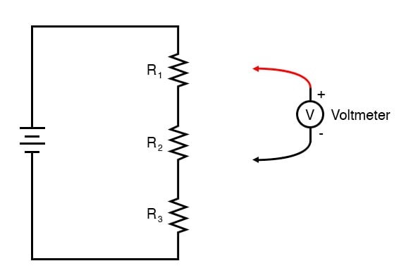
Figure 2. Schematic diagram of a voltage divider circuit.
Build the Voltage Divider Circuits
Below, we will demonstrate the three different construction techniques for building basic circuits like this voltage divider:
- Breadboard
- Terminal strip
- Free-form
Try building the same circuit using all three methods to familiarize yourself with the different construction techniques and their respective merits. Each of these methods implements the same circuit as shown in the schematic of Figure 2.
The breadboard construction, illustrated in Figure 3, is versatile and allows for high component density (many parts in a small space) but is quite temporary.
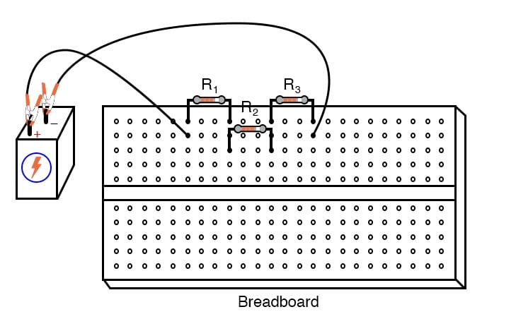
Figure 3. Breadboard implementation of a voltage divider circuit.
Figure 4 illustrates the connection of the voltage divider using terminal strips. These terminal strips provide a much more permanent form of construction at the cost of low component density.
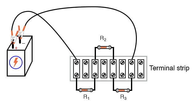
Figure 4. Terminal strip implementation of a voltage divider circuit.
The free-form method—where all components are connected together with alligator-style clips and jumper wires—is the least professional but is appropriate for a simple experiment such as this (Figure 5).
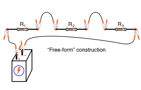
Figure 5. Free-form implementation of a voltage divider circuit.
Measure the Battery Voltage Under Load
Step 3: Measure the battery voltage with a voltmeter and record this as well, as it may differ slightly from a no-load condition. We saw this effect exaggerated in the parallel battery experiment while powering a high-wattage lamp. The battery voltage tends to “sag” or “droop” under load.
Although this three-resistor circuit should not present a heavy enough load (not enough current drawn) to cause significant voltage “sag,” measuring the battery voltage under load is a good scientific practice because it provides more realistic data.
Calculate and Measure the Current
Step 4: Use Ohm’s law applied to series circuits to calculate the circuit current.
$$I = \frac{V_{battery}}{R_1 + R_2 + R_3}$$
Step 5: Then verify this calculated value by measuring the current with an ammeter, as shown in Figure 6, for the terminal strip version of the circuit.
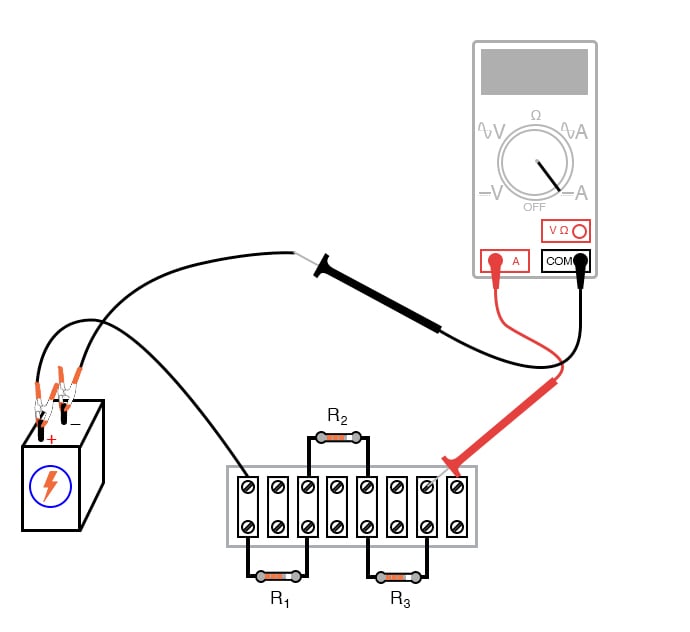
Figure 6. Using an ammeter to measure current in a voltage divider circuit.
If your resistor values are indeed between 1 kΩ and 100 kΩ, and the battery voltage is approximately 6 V, the current should be a very small value in the milliamp (mA) or microamp (µA) range.
When you measure current with a digital meter, the meter may show the appropriate metric prefix symbol (m or µ) in some corner of the display. These metric prefixes are easy to overlook when reading the display of a digital meter, so pay close attention!
Calculate and Measure the Voltage Drops
Step 6: Now, take that calculated value for current and multiply it by the resistance of each resistor to predict their voltage drops (V = IR).
Step 7: Switch your multimeter to the voltage mode and measure the voltage dropped across each resistor, verifying the accuracy of your predictions. Again, there should be close agreement between the calculated and measured voltage figures.
Each resistor voltage drop will be some fraction or percentage of the total voltage, thus this circuit’s name, a voltage divider. This fractional value is determined by the ratio of the resistance of the particular resistor and the total resistance.
If a resistor drops 50% of the total battery voltage in a voltage divider circuit, that proportion of 50% will remain the same as long as the resistor values are not altered. So, if the total voltage is 6 V, the voltage across that resistor will be 50% of 6 or 3 V. If the total voltage is 20 V, that resistor will drop 50% of 20 V, which is 10 V.
The equation for the voltage divider ratio of our three resistor circuits is given:
$$V_n = \left( \frac{R_n}{R_1 + R_2 + R_3} \right) \cdot V_{source}$$
Where n = 1, 2, or 3 for the voltage drop across an individual resistor.
Kirchhoff’s Voltage Law (KVL) Experimental Validation
The next part of this experiment is validating KVL.
Step 8: For this, you first need to identify each unique point in the circuit with a number. Electrically common points (directly connected to each other with insignificant resistance between the, as with a wire) use the same number.
An example using the numbers 0 through 3 is shown here in both illustrative (Figure 7).
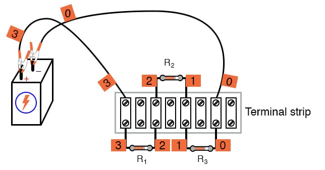
Figure 7. Adding node number tags to a voltage divider circuit.
While Figure 8 shows the same example but in a schematic form.
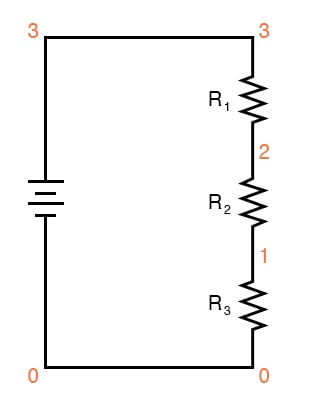
Figure 8. Node numbers added to the voltage divider circuit schematic.
In these figures, zero is commonly used for the ground node, which is required for many SPICE circuit simulators. In the illustration of Figure 7, we can see how points in the circuit may be labeled with small pieces of tape using numbers written on the tape.
Step 9: Using a digital voltmeter (this is important!), measure voltages around the loop formed by the points 0 to 1, 1 to 2, 2 to 3, and 3 to 0. Write on paper each of these voltages, along with its respective sign as indicated by the meter. In other words, if the voltmeter registers a negative voltage, such as -1.325 volts, you should write that figure as a negative number.
Do not reverse the meter probe connections with the circuit to make the number read “correctly.” The mathematical sign is very significant in this phase of the experiment! Analog voltmeters do not work with negative voltages, which is why you need a digital voltmeter for this part of the lab.
Here is a sequence of illustrations (Figures 9 through 12) showing how to step around the circuit loop, starting and ending at point 0.
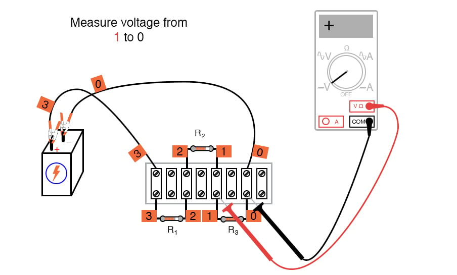
Figure 9. Measuring the first voltage drop in the voltage divider circuit.
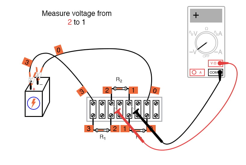
Figure 10. Measuring the second voltage drop in the voltage divider circuit.
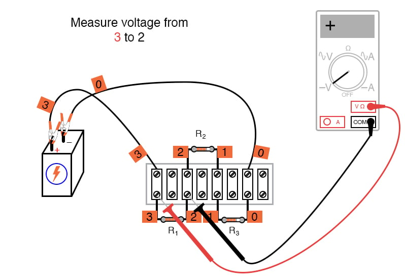
Figure 11. Measuring the third voltage drop in the voltage divider circuit.
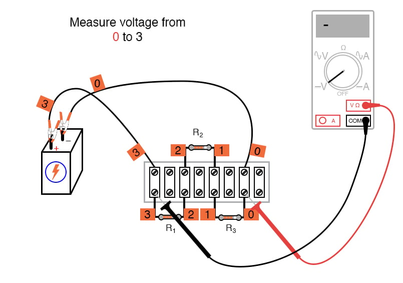
Figure 12. Measuring the fourth voltage drop in the voltage divider circuit.
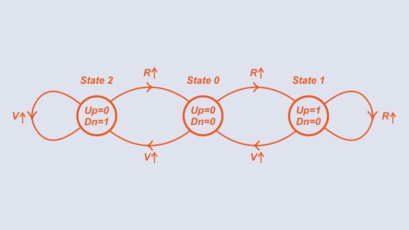
Using the voltmeter to “step” around the circuit in this manner yields three positive voltage figures and one negative, as illustrated in Figure 13.
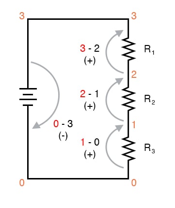
Figure 13. Demonstrating KVL from voltage measurements of the voltage divider circuit.
When algebraically added (algebraically means including the signs of the numbers), the sum of these four voltages should equal zero. This is the fundamental principle of KVL: the algebraic sum of all voltage drops in a “loop” adds to zero.
Using KVL on Non-standard Loops
It is important to realize that the loop stepped around does not have to be the same path that the current takes in the circuit or even a legitimate current path at all. The loop where we tally voltage drops can be any collection of points so long as it begins and ends with the same point.
For example, we may measure and add the voltages in the loop 1-2-3-1, and they will form a sum of zero as well as shown in Figure 14.
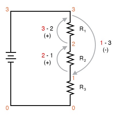
Figure 14. Demonstrating KVL for a non-standard loop.
Step 10: Let’s try out KVL for that non-standard loop of Figure 14. Take the three voltage measurements shown in Figures 15, 16, and 17.
Figure 15. Demonstrating KVL - first measurement of the voltage divider circuit.
Figure 16. Demonstrating KVL - second measurement of the voltage divider circuit.
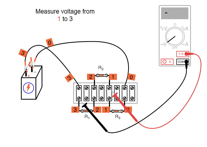
Figure 17. Demonstrating KVL - third measurement of the voltage divider circuit.
Step 11: Now, add those three voltages again, paying attention to the sign of the value. The sum will be zero if you have taken and recorded the measurements correctly.
Try stepping between any set of points, in any order, around your circuit and see for yourself that the algebraic sum always equals zero. KVL holds true no matter what the configuration of the circuit: series, parallel, series-parallel, or even an irreducible network.
Review of the Voltage Divider Experimental Measurements
KVL is a powerful concept, allowing us to predict the magnitude and polarity of voltages in a circuit by developing mathematical equations for analysis based on the truth of all voltages in a loop adding up to zero.
This experiment is intended to give empirical evidence for and a deep understanding of KVL as a general principle. It also demonstrates how a voltage divider
SPICE Simulation of the Voltage Divider Circuit
We can also simulate the voltage divider circuit using a SPICE circuit simulator using the following netlist. Create a text file containing the following text verbatim:
Voltage divider
v1 3 0
r1 3 2 5k
r2 2 1 3k
r3 1 0 2k
.dc v1 6 6 1 * Voltages around 0-1-2-3-0 loop algebraically add to zero:
.print dc v(1,0) v(2,1) v(3,2) v(0,3) * Voltages around 1-2-3-1 loop algebraically add to zero:
.print dc v(2,1) v(3,2) v(1,3)
.end
This computer simulation is based on the point numbers shown in the previous diagrams for illustrating KVL (points 0 through 3).
Resistor values were chosen to provide 50%, 30%, and 20% proportions of total voltage across R1, R2, and R3, respectively. Feel free to modify the voltage source value (in the “.dc” line, shown here as 6 volts) and/or the resistor values.
When run, SPICE will print a line of text containing four voltage figures, then another line of text containing three voltage figures, along with lots of other text lines describing the analysis process. Add the voltage figures in each line to see that the sum is zero.
Related Content
Learn more about the fundamentals behind this project in the resources below.
Calculators:
Worksheets:
Textbook:
Video Tutorials and Lectures:
- Series Circuits Part 1
- Series Circuits Part 2: Voltage Divider Equation
- Series Circuits Part 3: Series Voltage Sources