 Facebook
 Google
 GitHub
 Linkedin
DC Lab - 4-wire Resistance Measurement
Project Overview
Most ohmmeters operate on the principle of applying a small voltage across an unknown resistance (Runknown) and inferring resistance from the amount of current drawn by it. As illustrated in Figure 1, this presents a problem for measuring low resistances, as a low-resistance specimen may be a much smaller resistance value than the meter circuitry itself.
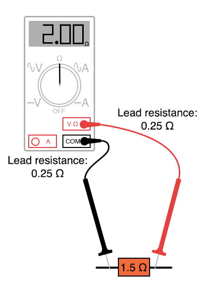
Figure 1. The challenge of measuring low resistance values.
Being part of the measurement circuit, the test leads may contain more resistance than the resistance of the test specimen, incurring significant measurement errors by their presence.
In the example of Figure 1, the reported resistance of 2.0 Ω is too large by 0.5 Ω. This is 33% larger than the 1.5 Ω of the device under test. For smaller resistances, the percentage error becomes even larger. One of the many sources of error in measuring small resistances with an ordinary ohmmeter is the resistance of the ohmmeter’s own test leads.
Imagine trying to measure the diameter of a cotton thread with a yardstick or measuring the weight of a coin with a scale built for weighing freight trucks, and you will appreciate the problem at hand.
Parts and Materials
- 6-volt battery or power supply
- A low-value resistor (< 1 Ω), a large spool of wire, or the electromagnet constructed in a previous experiment
- It would be ideal in this experiment to have two meters: one voltmeter and one ammeter. For experimenters on a budget, this may not be possible.
In this experiment, a 6 V lantern battery will essentially be short-circuited by a long piece of wire. This may produce currents of several amps in magnitude. Whatever ammeter is used should be capable of measuring at least 5 A. Keep in mind that your ammeter needs to be capable of measuring this current without blowing a fuse or sustaining other damage.
Learning Objectives
- The operating principle of Kelvin (4-wire) resistance measurements
- How to measure low resistances with common test equipment
The Kelvin, or 4-wire, Resistance Measurement Method
The Kelvin resistance measurement method involves using an ammeter and voltmeter, as illustrated in the circuit schematic of Figure 2.
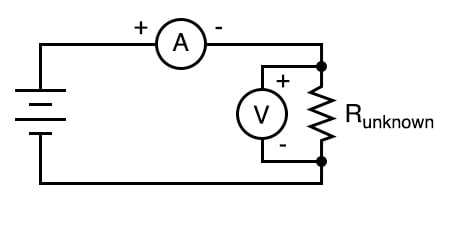
Figure 2. Schematic diagram of a 4-wire Kelvin resistance measurement.
This method is also called a 4-wire resistance measurement because four wires are connected to the unknown resistance—two at each end. A current is passed through the ammeter and the unknown resistance. The voltage dropped across the resistance is measured by the voltmeter, and resistance is calculated using Ohm’s Law (R = V/I)
Since only the voltage dropped by the unknown resistance is factored into the calculation—not the voltage dropped across the ammeter’s test leads or any other connecting wires carrying the main current—errors otherwise caused by these stray resistances are completely eliminated. Very small resistances may be measured easily by using large current as this generates a larger, more easily measured, voltage drop from which to infer resistance than if a small current were used.
Instructions
This experiment is best performed with two meters (one ammeter and one voltmeter), as illustrated in the circuit schematic of Figure 2. This is how production 4-wire resistance is performed. However, as we will demonstrate below, one multimeter is sufficient.
Step 1: Select a suitably low-resistance specimen to use in this experiment. One suggestion is to use the electromagnet coil specified in a previous experiment or a spool of wire where both ends may be accessed.
Step 2: Measure the resistance directly using the ohmmeter function. We will compare this 2-wire measurement value with the value we determine from our 4-wire measurement.
Step 3: Connect a 6 V battery to this specimen, with an ammeter connected in series, as illustrated in Figure 3. WARNING: The ammeter should be capable of measuring at least 5 A of current so that it will not be damaged by the (possibly) high current generated in this near-short circuit condition.
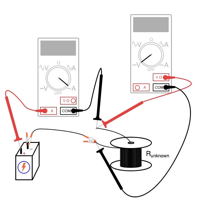
Figure 3. Using the 4-wire Kelvin resistance measurement technique to measure a low resistance value.
Next, if you have a second meter, proceed to Step 4. If you have only a single multimeter, skip Step 4 and move to Step 5.
Step 4: With the second meter, use it to measure the voltage across the resistance specimen’s connection points, as shown in Figure 3, and record both the current and voltage reported. Proceed to Step 6.
Step 5A: If you have only one meter, use it to measure current first, recording its indication as quickly as possible, then immediately opening (breaking) the circuit. You don’t want to leave the battery connected to the specimen for any longer than necessary for obtaining meter measurements, as it will begin to rapidly discharge due to the high circuit current. This discharge could compromise the measurement accuracy when the meter is re-configured and the circuit closed once more for the next measurement. When two meters are used, this is not as significant an issue because the current and voltage indications may be recorded simultaneously.
Step 5B: Next, switch the meter to its voltage mode, connect it across the specimen’s connection points, and re-connect the battery, quickly noting the voltage indication.
Step 6: Take the voltage measurement and divide it by the current measurement to calculate the specimen’s resistance in ohms from our 4-wire Kelvin measurement:
$$R = \frac{V}{I}$$
Step 7: Compare this 4-wire resistance value with the earlier 2-wire resistance measurement. Are they different? Why?
Related Content
Learn more about the fundamentals behind this project in the resources below.
Calculators:
Textbook Pages:
Worksheets:


This is a dangerous set-up. Just use a 12V circuit with a automotive bulb in series, to produce an approximate current of 1A (12 Watt bulb) and the resulting millivolt (s) correspond directly, lineair proportionally to milli-ohms of the circuit measured.