Facebook
 Google
 GitHub
 Linkedin
Intro Lab - Ohm’s Law
Project Overview
This project employs all of the skills explained earlier in this textbook for using an ohmmeter, voltmeter, and ammeter. You will build a simple circuit, as illustrated in Figure 1, to experimentally verify Ohm's law which defines the mathematical relationship between resistance, voltage, and current.
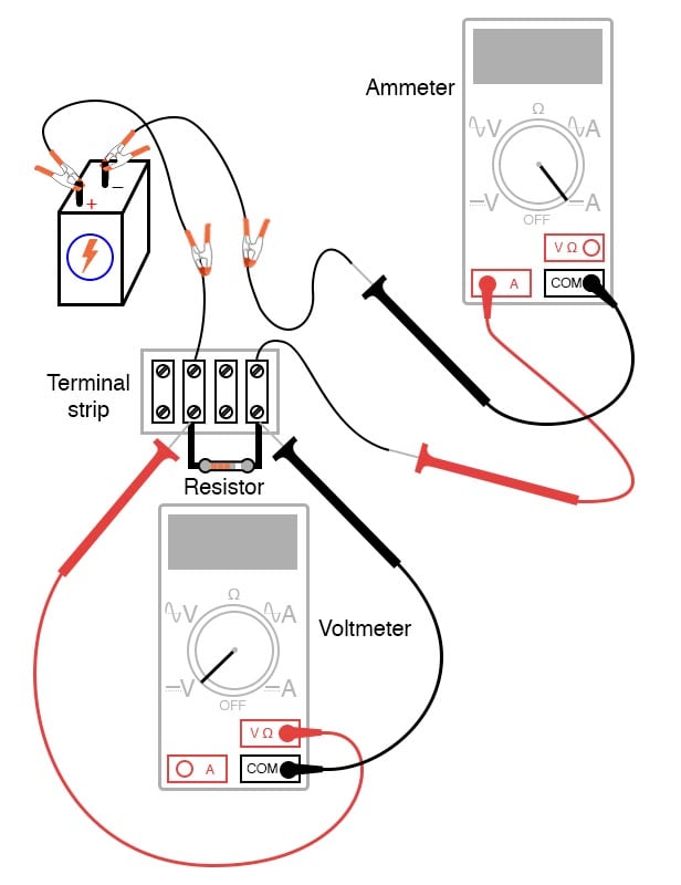
Figure 1. Test circuit for evaluating Ohm's law.
Parts and Materials
- 6 V battery
- Assortment of resistors between 1 kΩ and 100 kΩ in value
For this experiment, I’m purposely restricting the resistance values between 1 kΩ and 100 kΩ for the sake of obtaining accurate voltage and current readings with your meter.
With very low resistance values, the internal resistance of the ammeter has a significant impact on measurement accuracy. Very high resistance values can cause problems for voltage measurement since the internal resistance of the voltmeter substantially changes circuit resistance when it is connected in parallel with a high-value resistor. At the recommended resistance values, there will still be a small amount of measurement error due to the impact of the meter, but not enough to cause serious disagreement with calculated values.
Learning Objectives
- Application of Ohm’s law
- Voltmeter use
- Ammeter use
- Ohmmeter use
Instructions
Step 1: Select a resistor from the assortment, and measure its resistance, R, with your multimeter set to the appropriate resistance range. Be sure not to hold the resistor terminals when measuring resistance, or else your hand-to-hand body resistance will influence the measurement! Record this resistance value for future use.
Step 2: Next, build the one-battery, one-resistor circuit, shown in the schematic diagram of Figure 2.
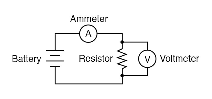
Figure 2. Test circuit schematic diagram for evaluating Ohm's law.
If you have two multimeters, you can construct exactly as shown in Figures 1 and 2 and measure both voltage and current simultaneously. However, in the following descriptions, we will assume you have only one multimeter and will perform the measurements in steps.
A terminal strip implementation of this circuit is demonstrated in Figure 1, but you can also use a breadboard or any other type of circuit construction method.
Step 3: Set your multimeter to the appropriate voltage range and measure the voltage, V, across the resistor as it is being powered by the battery. Record this voltage value.
Step 4: Set your multimeter to the highest current range available. Break the circuit and connect the ammeter within that break, so it becomes a part of the circuit, in series, with the battery and resistor.
Step 5: Select the best current range; whichever one gives the strongest meter indication without over-ranging the meter. If your multimeter is autoranging, of course, you need not bother with setting ranges. Record this current value along with the resistance and voltage values previously recorded.
Step 6: Taking the measured figures for voltage and resistance, use Ohm’s law equation to calculate circuit current.
$$I = \frac{V}{R}$$
Where:
- I = current in amps (A)
- V = voltage in volts (V)
- R = resistance in ohms (Ω)
Compare this calculated figure for the current with the measured figure for the circuit current. They should be identical (or very nearly so).
Step 7: Taking the measured figures for voltage and current, use Ohm’s law equation to calculate circuit resistance. Compare this calculated figure with the measured figure for circuit resistance.
$$R = \frac{V}{I}$$
Step 8: Finally, taking the measured figures for resistance and current, use Ohm’s law equation to calculate circuit voltage. Again, compare this calculated figure with the measured figure for circuit voltage.
$$V = I \cdot R$$
There should be close agreement between all measured and all calculated figures. Any differences in respective quantities of voltage, current, or resistance are most likely due to meter inaccuracies. These differences should be rather small, no more than several percent. Some meters, of course, are more accurate than others!
Step 9: Select different resistors are repeat steps 1 through 8. Re-take all resistance, voltage, and current measurements. Then, re-calculate these figures and check for agreement with the experimental data (measured quantities).
Also, note the simple mathematical relationship between changes in resistor value and changes in circuit current. Voltage should remain approximately the same for any resistor size inserted into the circuit because it is the nature of a battery to maintain voltage at a constant level.
Related Content
Learn more about the fundamentals behind this project in the resources below.
Textbook:
Calculator:
Worksheets:
- Ohm's Law Worksheet
- Simple Circuits Worksheet
- Elementary Circuits Worksheet
- Basic Voltmeter Use Worksheet
- Basic Ohmmeter Use Worksheet
- Basic Ammeter Use Worksheet