Facebook
 Google
 GitHub
 Linkedin
Intro Lab - Nonlinear Resistance
Project Overview
In this project, you will employ the circuit of Figure 1 to learn how the resistance of a device may change as a function of the voltage or current; that is, the resistance is nonlinear.
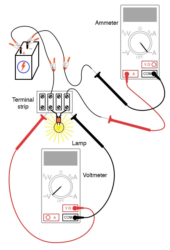
Figure 1. Nonlinear resistance circuit project setup.
This project uses the same parts and materials as the simple lighting project. It also employs the skills explained earlier in this textbook for using an ohmmeter, voltmeter, and ammeter.
Parts and Materials
- 6 V battery
- Low-voltage incandescent lamp
Learning Objectives
- Voltmeter use
- Ammeter use
- Ohmmeter use
- Use of Ohm’s law
- The realization that some resistances are unstable!
- Scientific method
Instructions
Step 1: With the lamp unconnected to a circuit, measure the resistance (Roff) of the lamp with your multimeter. This resistance figure is due to the thin metal filament inside the lamp. It has substantially more resistance than a jumper wire but less than any of the resistors from Ohm's law experiment. Record this resistance value for future use.
Step 2: Build the one-battery, one-lamp circuit shown in the circuit schematic of Figure 2.
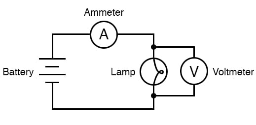
Figure 2. The schematic diagram for the nonlinear resistance circuit project.
You can build it using terminal strips as illustrated in Figure 1, or use a breadboard,
Step 2: Set your multimeter to the appropriate voltage range and measure the voltage across the lamp as it is energized (lit). Record this voltage value (V).
Step 3: Set your multimeter to the highest current range available. Break the circuit and connect the ammeter within that break, so it becomes a part of the circuit, in series, with the battery and lamp.
Step 4: Now, select the best current range, whichever one gives the strongest meter indication without over-ranging the meter. If your multimeter is autoranging, of course, you need not bother with setting ranges. Record this current value (I) along with the resistance and voltage values previously recorded.
Step 5: Taking the measured figures for voltage and current, use Ohm’s law equation to calculate the resistance when the lamp is turned on.
$$R_{on} = \frac{V}{I}$$
Where:
- Ron = resistance in ohms (Ω) when lamp is on
- I = current in amperes (A)
- V = voltage in volts (V)
Compare the two resistance values: Roff and Ron. What you should find is a marked difference between the measured resistance when the lamp is off and the calculated resistance; the on-resistance value is much greater. Why is this?
Step 6: To make things more interesting, try measuring the lamp’s resistance again, this time using a different model of meter. You will need to disconnect the lamp from the battery circuit in order to obtain a resistance reading because voltages outside of the meter interfere with resistance measurement. This is a general rule that should be remembered: measure resistance only on an unpowered component!
Using a different ohmmeter, the lamp will probably register as a different value of resistance. Usually, analog meters give higher lamp resistance readings than digital meters.
This behavior is very different from that of the resistors in the last experiment. Why? What factor(s) might influence the resistance of the lamp filament, and how might those factors be different between conditions of lit and unlit or between resistance measurements taken with different types of meters?
This problem is a good test case for the application of scientific methods. Once you’ve thought of a possible reason for the lamp’s resistance changing between lit and unlit conditions, try to duplicate that caused by some other means.
For example, if you think the lamp resistance might change as it is exposed to light (its own light, when lit) and that this accounts for the difference between the measured and calculated circuit currents, try exposing the lamp to an external source of light while measuring its resistance. If you measure substantial resistance change from light exposure, then your hypothesis has some evidential support.
If not, then your hypothesis has been falsified, and another cause must be responsible for the change in circuit current.
Related Content
Learn more about the fundamentals behind this project in the resources below.
Calculators:
Textbook:
Worksheets: