Facebook
 Google
 GitHub
 Linkedin
Intro Lab - Build an Electromagnet
Project Overview
In this project, you will build and test the electromagnet circuit illustrated in Figure 1. Electromagnetism has many applications, including:
- Relays
- Electric motors
- Solenoids
- Doorbells
- Buzzers
- Computer printer mechanisms
- Magnetic media write heads (tape recorders and disk drives)
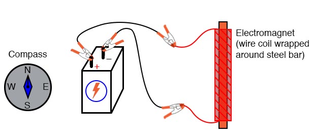
Figure 1. Electromagnet circuit for generating a magnetic field from an electric current.
Parts and Materials
- 6 V battery
- Magnetic compass
- Small permanent magnet
- Spool of 28-gauge magnet wire
- Large bolt, nail, or steel rod
- Electrical tape
Magnet wire is a term for thin-gauge copper wire with enamel insulation instead of rubber or plastic insulation. Its small size and very thin insulation allow for many turns to be wound in a compact coil. Keep in mind that you will need enough magnet wire to wrap hundreds of turns around the bolt, nail, or other rod-shaped steel forms.
Another thing, make sure to select a bolt, nail, or rod that is magnetic. Stainless steel, for example, is non-magnetic and will not function for the purpose of an electromagnet coil! The ideal material for this experiment is soft iron, but any commonly available steel will suffice.
Learning Objectives
- Application of the left-hand rule
- Electromagnet construction
Instructions
Step 1: Wrap a single layer of electrical tape around the steel bar (or bolt or mail) to protect the wire from abrasion.
Step 2: Proceed to wrap several hundred turns of wire around the steel bar, making the coil as even as possible. It is okay to overlap wire, and it is okay to wrap in the same style that a fishing reel wraps the line around the spool. The only rule you must follow is that all turns must be wrapped around the bar in the same direction (no reversing from clockwise to counter-clockwise!).
I find that a drill press works as a great tool for coil winding: clamp the rod in the drill’s chuck as if it were a drill bit, then turn the drill motor on at a slow speed and let it do the wrapping! This allows you to feed wire onto the rod in a very steady, even manner.
Step 3: After you’ve wrapped several hundred turns of wire around the rod, wrap a layer or two of electrical tape over the wire coil to secure the wire in place.
Step 4: Scrape the enamel insulation off the ends of the coil wires to expose the wire for connection to jumper leads
Step 5: Connect the coil to a battery, as illustrated in Figure 1 and defined in the circuit schematic of Figure 2.

Figure 2. Schematic diagram of the electromagnet circuit.
Step 6: When the electric current goes through the coil, it will produce a strong magnetic field with one pole at each end of the rod. This phenomenon is known as electromagnetism. With the electromagnet energized (connected to the battery), use the magnetic compass to identify the north and south poles of the electromagnet.
Step 7: Place a permanent magnet near one pole and note whether there is an attractive or repulsive force.
Step 8: Reverse the orientation of the permanent magnet and repeat steps 7 and 8. Note the difference in force caused by changing the polarity of the applied voltage and the direction of the current flow.
Inductive Kickback
You might notice a significant spark whenever the battery is disconnected from the electromagnet coil, much greater than the spark produced if the battery is short-circuited. This spark results from a high-voltage surge created whenever current is suddenly interrupted through the coil.
The effect is called inductive kickback and can deliver a small but harmless electric shock. To avoid receiving this shock, do not place your body across the break in the circuit when de-energizing. Use one hand at a time when un-powering the coil, and you’ll be perfectly safe.
Related Content
Learn more about the fundamentals behind this project in the resources below.
Textbook:
Worksheets:
- Basic Electromagnetism and Electromagnetic Induction Worksheet
- Intermediate Electromagnetism and Electromagnetic Induction Worksheet
- Advanced Electromagnetism and Electromagnetic Induction Worksheet