 Facebook
 Google
 GitHub
 Linkedin
Intro Lab - How to Use an Ammeter to Measure Current
Project Overview
In this project, you will learn how to use an ammeter to measure electrical current (the flow of electricity). Typically, the ammeter is one of the functions of a multimeter, which is an electrical instrument capable of measuring voltage, current, and resistance (Figure 1).
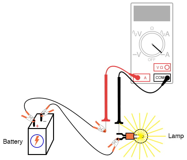
Figure 1. Ammeter test probe connections for measuring current.
Parts and Materials
- 6 V battery
- 6 V incandescent lamp
Basic circuit construction components such as breadboard, terminal strip, and jumper wires are also assumed to be available from now on, leaving only components and materials unique to the project listed under “Parts and Materials.”
Learning Objectives
- How to measure current with a multimeter
- How to check a multimeter’s internal fuse
- Selection of proper meter range
Introduction to Measuring Current
Current is the measure of the rate of electron “flow” in a circuit. It is measured in the unit of the Ampere, called “Amp,” (A). The most common way to measure current in a circuit is to break the circuit open and insert an ammeter in series (in-line) with the circuit so that all electrons flowing through the circuit must also go through the meter. Since measuring current in this manner requires the meter to be made part of the circuit, it is a more difficult type of measurement to make than either voltage or resistance.
Some digital meters, like the unit shown in Figure 1, have a separate A jack to insert the red test lead plug when measuring current. This is different than the connection points for measuring voltage and resistance. Other meters, like most inexpensive analog meters, use the same jacks for measuring voltage, resistance, and current. Consult your owner’s manual on the particular model of meter you own for details on measuring current.
When an ammeter is placed in series with a circuit, it ideally drops no voltage as current goes through it. In other words, it acts very much like a piece of wire, with very little resistance from one test probe to the other.
Ammeter Fuses for High Current Protection
Since an ammeter has very little resistance, it will act as a short circuit if placed in parallel (across the terminals of) a substantial voltage source. If this is done, a surge in current will result, as shown in Figure 2, potentially damaging the meter.
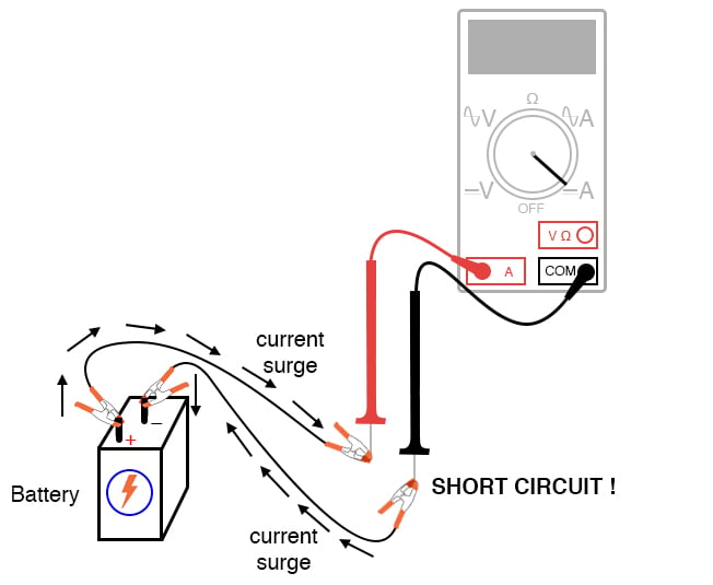
Figure 2. Ammeter short circuit connection resulting in a surge current.
Ammeters are generally protected from excessive current by means of a small fuse located inside the meter housing. If the ammeter is accidentally connected across a substantial voltage source, the resultant surge in current will blow the fuse and render the meter incapable of measuring current until the fuse is replaced. Be very careful to avoid this scenario!
Step 1: You may test the condition of a multimeter’s fuse by switching it to the resistance mode and measuring continuity through the test leads (and through the fuse). On a meter where different jacks are used for current, insert the test lead plugs, as illustrated in Figure 3, to check the fuse.
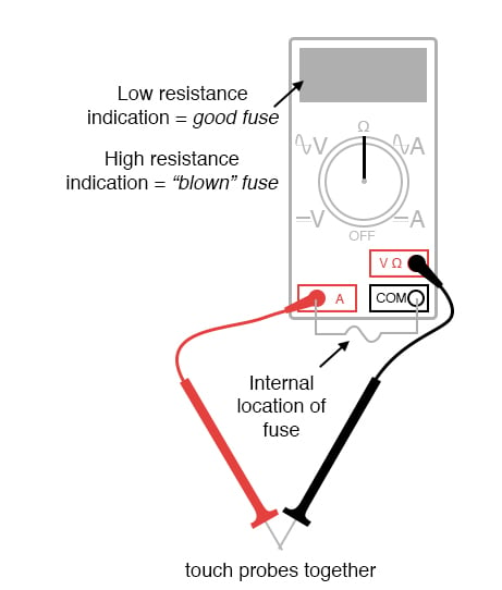
Figure 3. Testing an ammeter's fuse.
On a meter where the same test lead jacks are used for both resistance and current measurement, leave the test lead plugs where they are and touch the two probes together.
Step 2: Build the one-battery, one-lamp circuit using jumper wires to connect the battery to the lamp. You will omit the ammeter from the illustration of Figure 1 and the schematic diagram of Figure 4.

Figure 4. The schematic diagram for measuring the current of the lamp circuit using an ammeter.
Step 3: Verify that the lamp lights up before connecting the ammeter in series with it.
Step 4: Break the circuit open, as illustrated in Figures 1 and 3, and connect the ammeter’s test probes to the two points of the break to measure current. As usual, if your meter is manually ranged, begin by selecting the highest range for current. Next, move the selector switch to lower range positions until the strongest indication is obtained on the meter display without over-ranging it. If the meter indication is backward (left motion on an analog needle or negative reading on a digital display), then reverse the test probe connections and try again.
When the ammeter indicates a normal reading (not “backwards”), the current enters the red test lead and exits the black test lead. This is how you determine the direction of current using a meter.
For a 6 V battery and a small lamp, the circuit current will be in the range of thousandths of an amp or milliamps (mA). Digital meters often show a small letter “m” on the right-hand side of the display to indicate this metric prefix.
Step 5: Try breaking the circuit at some other point and inserting the ammeter there instead. What do you notice about the amount of current measured? Why do you think this is?
Connecting an Ammeter to a Breadboard Circuit: Tips and Tricks
Step 6: Re-construct the circuit on a breadboard, as illustrated in Figure 5. Verify that the light turns on.
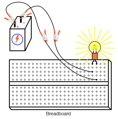
Figure 5. Breadboard implementation of the lamp circuit.
Students often get confused when connecting an ammeter to a breadboard circuit. How can the meter be connected so as to intercept all the circuit’s current and not create a short circuit?
One easy method that guarantees success is this:
- Identify what wire or component terminal you wish to measure the current through.
- Pull that wire or terminal out of the breadboard hole. Leave it hanging in mid-air.
- Insert a spare piece of wire into the hole you just pulled the other wire or terminal out of. Leave the other end of this wire hanging in mid-air.
- Connect the ammeter between the two unconnected wire ends (the two that were hanging in mid-air). You are now assured of measuring current through the wire or terminal initially identified.
Step 7: Follow the four-step sequence above to insert the ammeter into the breadboard lamp circuit. Your new circuit should look similar to the image in Figure 6.
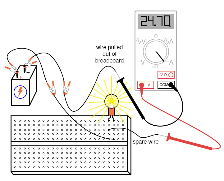
Figure 6. Breadboard implementation of the lamp circuit with an ammeter measuring current.
The current figure of 24.70 milliamps (24.70 mA), shown in Figure 6, is an arbitrary quantity but reasonable for a small incandescent lamp. If the current for your circuit is a different value, that is okay, so long as the lamp is functioning when the ammeter is connected.
If the lamp refuses to light when the ammeter is connected to the circuit, and the ammeter registers a much greater reading, you probably have a short-circuit condition through the ammeter. If your lamp refuses to light when the meter is connected to the circuit, and the meter registers zero current, you’ve probably blown the fuse inside the meter. If so, you will need to check the condition of your meter’s fuse as described previously in this experiment and replace the fuse if necessary.
Step 8: Measure the current through different wires in this circuit, following the same connection procedure outlined above. What do you notice about these current measurements? The results in the breadboard circuit should be the same as the results in the free-form (no breadboard) circuit.
Step 9: Build the same lamp circuit on a terminal strip, as illustrated in Figure 7, and measure the current. It should yield similar results.
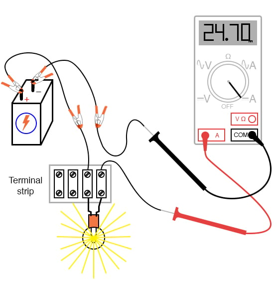
Figure 7. Terminal strip implementation of the lamp circuit with an ammeter measuring current.
Related Content
Learn more about the fundamentals behind this project in the resources below.
Textbook:
Worksheets:


If the multimeter dosnt specify which types of fuses it uses your probably better of buying a new modern.
I have dual replaceable fuses in mine, one of them can only handle 500mA at 600v. So It’s usually best to use the other circuit with the 10 Amp 600v rating if your unsure. They are both slow fuses so to be protected from short spikes in current or voltage. 😎
Btw when you messure current you only have two methods, either let the complete current flow through your measuring device or use a clamp version that measures the magnetic Flux and calculates the current based on the user’s set voltage value and the measured inductance.