 Facebook
 Google
 GitHub
 Linkedin
The CD4017: The Decade Counter That Taught a Generation Sequential Logic
RCA's 5-stage Johnson counter with 10 decoded outputs became one of the most built circuits in hobby electronics.
RCA introduced the CD4017 as part of its CD4000 COS/MOS CMOS logic family in the early 1970s. The device is a 5-stage Johnson decade counter with 10 decoded outputs in a 16-pin DIP. Its function is extremely straightforward: on each rising clock edge, exactly one of ten output pins goes high while the other nine stay low.
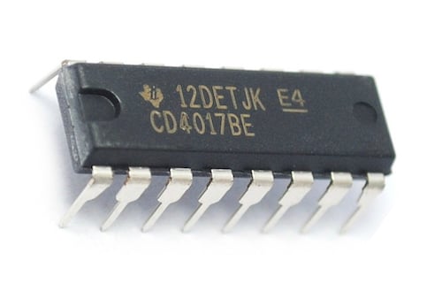
The CD4017 IC decade counter. Image used courtesy of Texas Instruments on Amazon
That one-hot sequential behavior, combined with the CD4000 family's 3–18-V supply range and near-zero static power draw, made the CD4017 the simplest way to build sequential logic without a microcontroller. Paired with an NE555 timer and ten LEDs, it produces a working LED chaser on a breadboard in under 20 minutes. Almost certainly the most replicated circuit among hobbyists, it remains in volume production today from Texas Instruments, Onsemi, and others.
Five Flip-Flops, Ten States
While a standard 5-bit binary counter would cycle through 32 states, the CD4017 uses a Johnson counter topology instead. This is a shift register in which the inverted output of the last stage feeds back into the input of the first, producing only 10 unique states from five flip-flops. Those 10 states, however, are internally decoded so that each one drives its own dedicated output pin. There’s no need for any external decoder because of this, and on every rising edge of the clock input (pin 14), the active-high output advances one position in sequence, from Q0 through Q9, then wraps back to Q0.

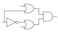
Functional diagram of the HEF4017B. Image used courtesy of Nexperia
The reset pin (pin 15) forces the counter back to Q0 when driven high, while the clock inhibit (pin 13) freezes the count when high, allowing external logic to pause the sequence. A carry-out on pin 12 stays high for the first five states (Q0-Q4) and drops low for the second five (Q5-Q9), completing one full cycle every ten clock pulses. That carry-out can clock a second CD4017, cascading two chips into a 100-state counter with no additional logic. Connecting any output pin to the reset pin converts the counter into a divide-by-N circuit for any value of N from 2 to 9.
Like the rest of the CD4000B family, the CD4017 runs from 3 V to 18 V with static current draw in the microwatt range. Propagation delay varies with supply voltage, from roughly 100 ns at 15 V down to slower operation at 3 V. Speed was never the point, though; the point was that every state had its own pin, and every pin could drive an LED directly.
NE555 and the CD4017: The Perfect Pair
The canonical CD4017 application pairs it with an NE555 timer running in astable mode. The 555 generates a continuous square wave whose frequency is set by two resistors and a capacitor. That clock signal feeds into the CD4017's pin 14, and the ten decoded outputs each drive an LED through a current-limiting resistor. That results in a sequential LED chaser whose speed can be adjusted in real time by swapping a resistor for a potentiometer.
This circuit appears in Don Lancaster's CMOS Cookbook (1977), in R.A. Penfold's 50 CMOS IC Projects (1977), and in virtually every hobbyist electronics tutorial published since.
Variations are endless. Adding diode steering between the outputs, for example, produces a bounce-back "Knight Rider" scanner pattern, while connecting an output to the reset pin shortens the sequence to any desired count. The NE555 and CD4017 pairing is also sold today as a prepackaged learn-to-solder kit from multiple vendors, typically for under $5.

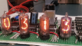
A soldering practice kit featuring a NE555 timer and CD4017 decade counter chips. Image used courtesy of ISolderStore Store on Amazon
Beyond LED chasers, the CD4017 has found use as a frequency divider in instrumentation, a channel selector for multiplexed sensor inputs, and a sequencer for irrigation and lighting controllers. Its decoded outputs eliminate the combinational logic that a binary counter like the CD4520 would require to drive individual loads, which is largely why the CD4017 became the default choice for hobbyist sequential circuits rather than technically superior alternatives.
What About Microcontrollers?
It’s true that an Arduino can easily replicate the CD4017's function in a few lines of code with fewer external components, and the cost difference between an ATmega328-based board and a CD4017 is negligible. Yet, the CD4017 remains in production, remains in kits, and remains the default for anyone teaching sequential logic to a beginner.
A big reason for this is undoubtedly transparency. A microcontroller hides the counting inside firmware, whereas the CD4017 shows it. Each state has a physical pin; each transition is a clock edge; and the entire behavior is visible on a schematic and verifiable with a battery and ten LEDs. No upload cable, no IDE, no debugging environment.
For teaching how a counter works rather than how to program one, that visibility has substantial value. Sure, the CD4017 didn’t invent the Johnson counter, and it was never the most capable counter in the CD4000 family, but it was the most legible—and that’s why it outlasted the era it was designed for.


I wonder how many readers don’t get the Knight Rider reference:)
I had a friend build a circuit, which I am sure was the one described, so he could have Knight Rider lights on his motorcycle. This was about 1983.