
 Facebook
 Google
 GitHub
 Linkedin
The NE555: The Timer That Refused to Quit
Born from a minimalist design brief in 1971, the NE555 delivered edge-triggered timing, pulse generation, and oscillation in one compact package, earning a place in everything from washing machines to rocket launchers.
By the early 1970s, engineers had oscillators, timers, and monostables, just not in one IC. Analog circuits using discrete parts were clunky, and existing timer chips lacked flexibility. That changed in 1971, when Hans Camenzind, working as a contractor for Signetics, designed a universal timing chip using just ~25 transistors, a few diodes, and a clever resistor-divider network.
The result was the NE555: an eight-pin analog timer that could generate one-shots, square waves, and flip-flops depending on how you wired it. It operated from a single supply, featured a powerful output stage, and was tolerant in noisy environments. Once Signetics released it, demand took off across hobby and industry alike.
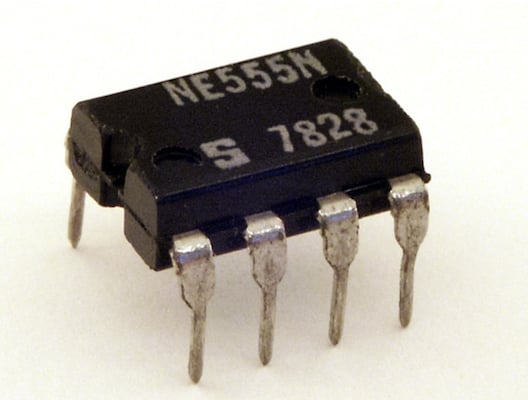
Signetics NE555 in an eight-pin DIP package. Image used courtesy of Stefan506 via Wikimedia Commons (CC BY-SA 3.0)
In the decades since, the 555 has shown up in LED flashers, motor drivers, servo testers, VCOs, debounce circuits, and more. Engineers have used it to control relays, play melodies, detect missing pulses, and keep watchdog timers honest. It has shipped in the tens of billions, and today’s CMOS versions continue the lineage, drawing far less current while preserving the mental model millions of engineers grew up with.
Inside the IC
The NE555’s genius lies in its internal partitioning. Three 5-kΩ resistors form a voltage divider between VCC and ground, setting two thresholds: 1/3 VCC and 2/3 VCC. These are fed to a pair of comparators, which in turn drive an SR latch. That latch controls an open-collector NPN transistor tied to the DISCH pin, which can dump the charge from an external capacitor to ground.
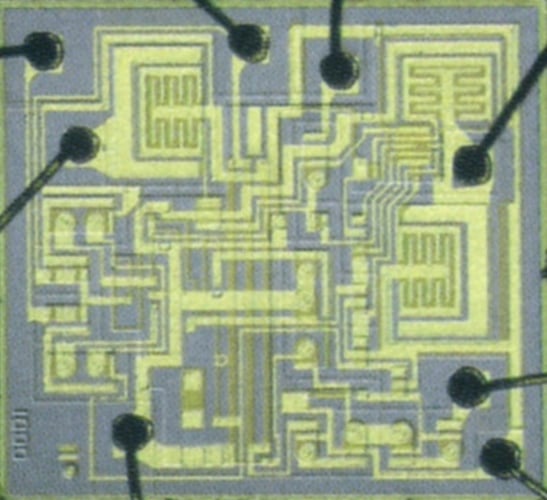
Silicon die of the first 555 chip in 1971. Image used courtesy of CQ Publishing Co., Ltd. via Wikimedia Commons (Public domain)
Depending on how you connect the pins, the 555 can operate in one of three core modes:
- Monostable (one-shot): A negative pulse on TRIG pulls the input below 1/3 VCC, setting the latch and turning the output high. The capacitor then charges through a resistor, and when it reaches 2/3 VCC, the latch resets and the output drops. The pulse width is given by t ≈ 1.1 RC.
- Astable (free-running): With a capacitor between ground and pin six (THRES), and two resistors (RA and RB) controlling charge/discharge time, the output oscillates continuously. The frequency is roughly f ≈ 1.44 / ((RA + 2RB) x C).
- Bistable (flip-flop): TRIG and THRES can be used as set/reset inputs, allowing the 555 to function as a basic memory element or debounced switch.
The IC also includes a CONTROL voltage pin that exposes the 2/3 VCC threshold for external modulation or PWM tricks. If unused, it’s typically bypassed to ground with a 10-nF capacitor to avoid instability.
One of the 555’s most useful design features is its output stage. A bipolar version can sink or source around 200 mA, enough to drive small loads directly, making it a favorite in low-part-count circuits long before microcontrollers became cheap and ubiquitous.
Why the 555 Still Has a Place On Modern Boards
For all its analog simplicity, the 555 continues to show up in new designs because it still makes sense to include it.
Where a microcontroller might be overkill, the 555 is a fast, deterministic, and rugged way to create pulses, delays, or blinking behavior with just a few passives. When CMOS versions like the TLC555 and LMC555 arrived, they extended the chip’s appeal into low-power, battery-operated, and rail-to-rail swing applications.
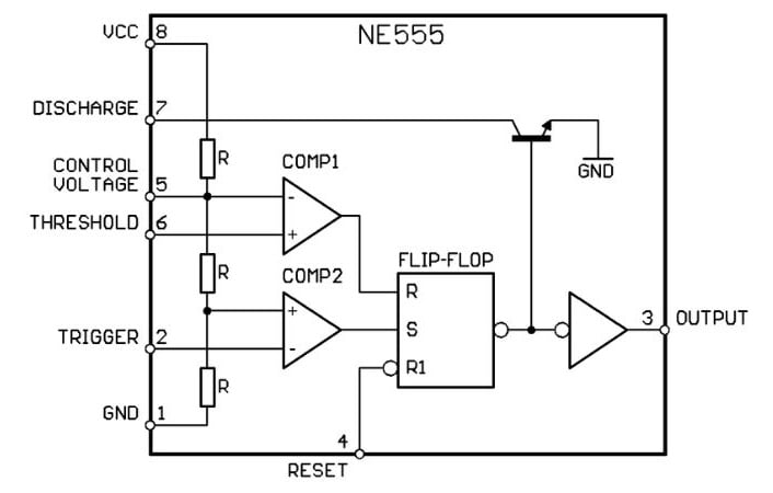
Block diagram of the NE555. Image (modified) used courtesy of NE555 astable.png via Wikimedia Commons (CC BY-SA 3.0)
Of course, there are tradeoffs. The bipolar NE555 can introduce VCC noise spikes due to its hefty output transitions. It also has asymmetric output drive strength and a minimum duty cycle above 50% in the basic astable mode, though a shunt diode across RB or an alternate topology can fix that.
Still, for engineers who grew up blinking LEDs with a 555 on a breadboard, the chip is a benchmark in analog elegance: No firmware, no initialization, just a few volts and a capacitor. And it still ships in volumes most digital ICs can only dream of.
Related Content










Just by reading this article I feel guilty just because I have never used a 555 in one of my electronic design..