Facebook
 Google
 GitHub
 Linkedin
The NE565: The Chip That Made the Phase-Locked Loop Practical
Signetics packed a VCO and phase detector into one 14-pin part, turning a daunting feedback technique into something an ordinary engineer could build.
Signetics introduced the NE565 in the early 1970s as the general-purpose member of its 560-series phase-locked loop family, the first commercially significant line of monolithic PLLs.
The phase-locked loop was nothing new as a concept, but until a single chip could hold the pieces together, building one meant assembling a voltage-controlled oscillator, a phase detector, and a filter from discrete parts that drifted with temperature and fought to stay tuned.
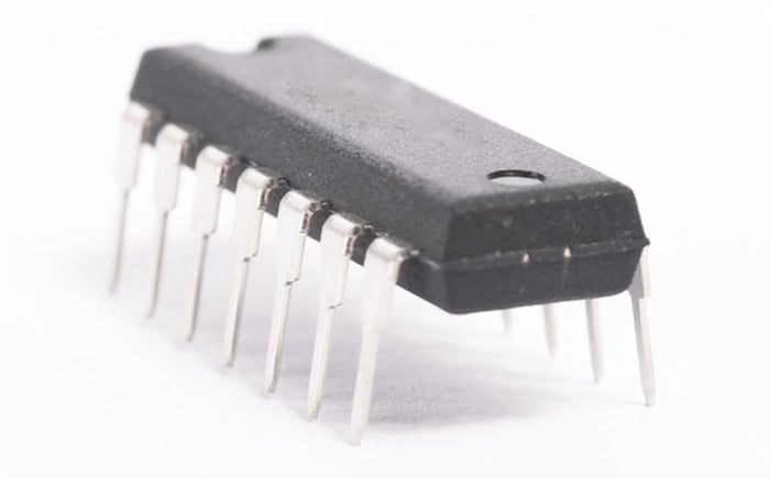
Signetics' NE565. Image used courtesy of Little Diode
The 565 put the oscillator, phase comparator, and amplifier on one die in a 14-pin DIP. In doing so, it moved the PLL out of the specialist's lab and onto the general engineer's bench.
Lock and Capture in One Package
A phase-locked loop works by comparing the phase of an incoming signal with that of an internal oscillator, then steering the oscillator until the two march in step. The NE565 exposes exactly those parts. An external resistor and capacitor set the free-running frequency of the internal VCO, following the relation f0 = 1.2 / (4·R1·C1), and a second external capacitor sets the loop's low-pass filter. From there, the chip does the rest, driving its oscillator to track an input anywhere within its lock range.
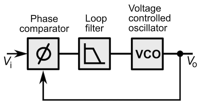
A schematic of a simple analog phase-locked loop. Image used courtesy of Chetvorno via Wikimedia Commons (CC0)
Two numbers define the behavior: the lock range is the band over which the loop, once locked, will follow a drifting input. On the 565, it scales with supply voltage as roughly +/-8·f0 / Vcc. The capture range, always narrower, is the band within which the loop can initially grab an unlocked signal. It’s governed by that external filter capacitor.
The part runs from a +/-6-V to +/-12-V dual supply and operates up to 500 kHz, modest by later standards but well matched to the audio and low-RF tasks it was built for. The clean separation of lock and capture, both adjustable with a couple of passive components, is what made the 565 such an effective teaching device as well as a working one.
Modems to Tone Decoders
The canonical NE565 application was frequency-shift keying. Early data modems and radio teletype encoded bits as two close audio tones, and recovering the data meant tracking which tone was present at any instant.
A PLL does this naturally: lock onto the incoming tone, and the control voltage that steers the VCO becomes the recovered data, swinging one way for a mark and the other for a space. The same trick demodulates FM, where the VCO control voltage follows the frequency deviation and reconstructs the original signal. Signetics also pitched the part for SCA decoding, the 67-kHz subcarrier that carried background music on FM stations, as well as telemetry and frequency multiplication.
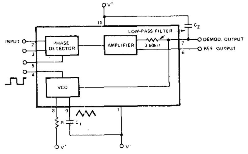
Block diagram of the NE565. Image used courtesy of Alldatasheets.com
However, the family's most enduring member was a close sibling, the NE567 tone decoder, which paired a PLL with a quadrature detector to pull its output low whenever a specific tone appeared at the input. Tone decoders of that kind ended up in remote controls, touch-tone detection, and countless hobbyist projects, and the 567 has stayed in production long after the 565 itself faded.
The 560-series also anchored a generation of textbooks and application notes, including Howard Berlin's Design of Phase-Locked Loop Circuits with Experiments, first published in 1978, which walked readers through the 565 and 567 with circuits they could actually wire up.
Obsolete Today
The NE565 itself is now largely obsolete, hard to find as a new part, and superseded by integrated solutions that hide the loop inside larger chips. Its importance was never about longevity, though.
Before the 565, the phase-locked loop was a technique that engineers respected and mostly avoided, a tangle of feedback theory that was difficult to realize reliably in hardware. After it, the PLL became a building block, something you could specify with two equations and three passive components and expect to work.
That shift in accessibility is the chip's ultimate legacy; a generation of engineers learned what lock and capture meant not from a derivation but from watching a 565 grab a tone and hold it, the control voltage tracking on an oscilloscope. So, while the part didn’t invent the phase-locked loop, it made the idea commonplace, and industry acceptance proliferated from that point on.