 Facebook
 Google
 GitHub
 Linkedin
What Exactly Is a Phase-Locked Loop, Anyways?
This article introduces a phase-based feedback system that plays an important role in many applications.
This article introduces a phase-based feedback system that plays an important role in many applications.
Most of us have seen the phrase “phase-locked loop” (or its abbreviation, PLL). I suspect, however, that relatively few of us thoroughly understand 1) the internal functionality of a PLL and 2) how this functionality leads to the various ways in which PLLs are used. My objective in this article is to provide a clear, intuitive explanation of fundamental PLL characteristics, and we’ll continue with additional articles that explore the details.
The term “phase-locked loop” appears in a variety of contexts: microcontrollers, RF demodulators, oscillator modules, serial communications. The first thing to understand is that “PLL” does not refer to a single component. A PLL is a system—it consists of multiple components that are carefully designed and interconnected in a negative-feedback configuration. It is true that PLLs are sold as a single integrated circuit, and thus it would be natural to think of them as a “component,” but don’t let this distract you from the fact that PLLs are analogous to (for example) an elaborate op-amp-based amplifier circuit, not to an op-amp itself.
PLL ≥ PD + LPF + VCO
Let’s start with a diagram:
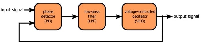
This is as basic as a PLL can be. Let’s discuss the three essential components.
- A phase detector is (unfortunately) not really a phase detector, but that’s the standard terminology. The phase detector in a PLL is actually a phase difference detector, i.e., it accepts two periodic input signals and produces an output signal representing the phase difference between the two inputs.
- The output of the phase detector is not a straightforward analog signal that is proportional to the phase difference. The straightforward analog signal is in there somewhere, but it’s combined with high-frequency content that makes the signal look very different from what you might expect. Hence the low-pass filter: it suppresses the higher-frequency components and transforms the phase detector’s output into something that can control a VCO.
- The voltage-controlled oscillator is, you guessed it, an oscillator controlled by a voltage. More specifically, the frequency of the periodic signal generated by the oscillator is controlled by a voltage. So the VCO is a variable-frequency oscillator that allows an external voltage to influence its frequency of oscillation. In the case of a PLL, the control voltage is a low-pass-filtered phase-detector signal.
Waveforms
Before we discuss the negative-feedback action, let’s move this discussion into the practical realm. We’re going to look at some waveforms produced by a digital PLL. You may envision a PLL as a primarily analog system, and that’s fine, but experimenting with a digital system is (in my opinion) more straightforward. The essential thing to keep in mind is that the same concepts apply to both analog and digital implementations. If you understand what’s happening with these digital waveforms, you understand PLL signals in general.
In a digital PLL, all you need for the phase detector is an XOR gate. As you know, an XOR gate produces a logic-high output only when the two inputs are different. If you extend this behavior to a situation in which both of the inputs are square waves, the XOR becomes an “out-of-phase detector”:
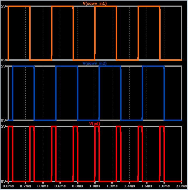
These two square waves have a small phase difference, and consequently they are at different logic states for a small portion of the cycle. When the logic states are different, the XOR output is high. If the phase difference becomes larger, the XOR output spends more time at logic high:
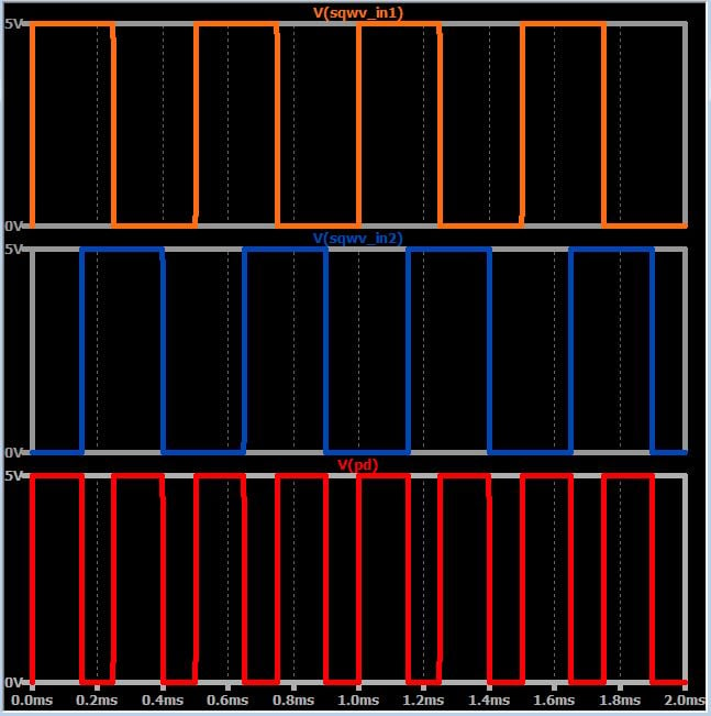
This is how an XOR gate functions as a phase detector: As the phase difference increases, the output spends a larger portion of the cycle at logic high. In other words, the duty cycle, and hence the average value, of the XOR output is proportional to the phase difference.
The next step is to use this average value as a control signal for the VCO, and this is where the low-pass filter comes in:
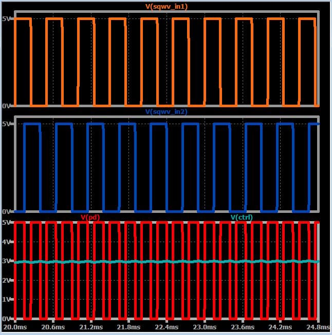
The green trace, which is the average value with a bit of ripple, is produced by passing the phase-detector signal through a simple RC low-pass filter (you may recognize this technique if you’ve used a “PWM DAC,” which is a digital-to-analog converter that functions by low-pass filtering a pulse-width-modulated signal). The trace is labeled “ctrl” because this is the signal that we can use to control (i.e., vary the frequency of) the VCO.
Closing the Loop
PLLs can be used in various clever ways, but the fundamental functionality is “locking” the output frequency to the input frequency. (They also lock the output phase to the input phase, as you would expect from the name “phase-locked loop,” but it’s a different sort of lock.) The locking action is made possible by negative feedback, i.e., by routing the output signal back to the phase detector (as shown in the above diagram).
In my experience, trying to thoroughly understand the exact process by which a PLL locks the output frequency to the input frequency is like trying to grab a piece of fog and hold it in your hand. It’s right there in front of you, and you know it’s real, and you know more or less what it is, but it slips away when you really try to observe it and comprehend it. We’ll discuss this process further in a future article. For now, I’ll leave you with some important points that will help you to ponder this interesting functionality.
- The phase detector will produce a constant duty cycle (and hence a constant average value) only when the two input frequencies are equal (as in the examples above). Different frequencies lead to periodic variations in the duty cycle:
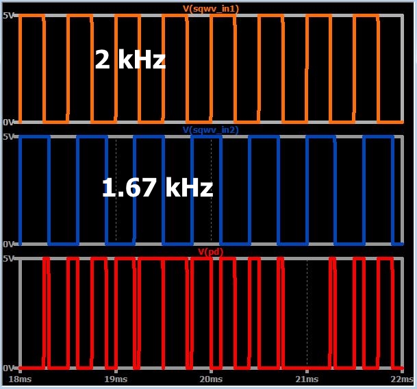
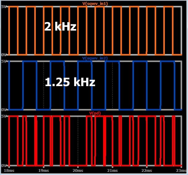
- Consequently, the control voltage will continue to wander up and down until the output frequency is equal to the input frequency.
- To establish lock, the PLL must do more than make the output frequency equal to the input frequency. It must also establish the input–output phase relationship that leads to the appropriate control voltage.
- The PLL has no way of directly controlling the phase of the VCO signal. The only way it can adjust the VCO phase is by adjusting the frequency, and thus frequency variations will continue until both frequency lock and phase lock have been achieved.
Conclusion
We’ve introduced the fundamental structure and some operational details of the phase-locked loop, which is a negative-feedback-based system that can generate a periodic signal that locks onto and tracks the frequency of an input signal. We will continue to explore PLL functionality and applications in future articles.


Thanks for the article, great!
very nice. thanks for your explanation. please continue about PLLs.
Great! Thank you.