 Facebook
 Google
 GitHub
 Linkedin
What Exactly Is a Quartz Crystal, Anyways? A Look at Quartz Crystal Oscillators
This article explains some theory behind an extremely common electronic component.
This article explains some theory behind an extremely common electronic component.
Wikipedia informs us that quartz is the second most abundant mineral on earth. It’s composed of silicon and oxygen (not exactly exotic elements) in a “continuous framework of SiO4 silicon–oxygen tetrahedra” (not sure what that means...). Based on this information, would you ever have thought that quartz crystals would become pervasive electronic components that function as the central element in countless high-performance oscillator circuits?
There is no doubt that you can use quartz crystals without knowing much about what they really are: You connect the crystal to some microcontroller pins, add a couple load capacitors, and you have an oscillator. However, I am generally of the opinion that it is not a great idea to know little or nothing about the components and subcircuits that we continually use in our designs.
Knowledge doesn’t exist in isolation. You may never need to know exactly why a piece of quartz can turn a feedback circuit into an oscillator, but this information is part of an extensive network of knowledge that leads us to an authentic understanding of fundamental electronic concepts. In other words, we sometimes need to resist the inclination to ignore the details—they might turn out to be little lines that connect big dots.
The Circuit
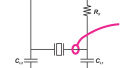
This is the equivalent circuit of a quartz crystal:
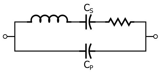
Let’s be clear: A quartz crystal is a quartz crystal. If you hit the crystal with a hammer it won’t break into an inductor, a resistor, and two capacitors. However, quartz crystals have (in my opinion rather mysterious) electromechanical characteristics that cause the crystal to behave, in the context of an electronic circuit, like the collection of passive components shown above.
All those components in the equivalent circuit are extremely common. You might be wondering, then, why we bother with a quartz crystal at all. Why not just use caps, inductors, and resistors in the same arrangement? Well, as we will see later, you could never achieve equivalent performance using passives, especially when you consider how small a quartz crystal is.
Resonance
Inductors and capacitors store energy. If you connect an inductor and capacitor in a way that allows energy to flow back and forth between the two components, you have a resonant circuit. In an idealized circuit this back-and-forth flow continues forever, and you would have an oscillator. In a real-life circuit the oscillations decrease in amplitude (and eventually cease) as energy is dissipated by resistive elements such as wires or PCB traces. More resistance means that the oscillations are more “damped,” i.e., the amplitude decreases more quickly. Q factor is inversely proportional to resistance, meaning that lower Q corresponds to oscillations that die away more quickly.
Resonance occurs in both series LC circuits and parallel LC circuits, and if you look back at the equivalent circuit, you can see that a crystal has both series and parallel resonance. The resonant frequency for the series-connected inductor and capacitor follows the standard formula:
$$ f_{SR}=\frac{1}{2\pi\sqrt{LC_S}}$$
The parallel resonance is a bit more complicated. This resonant frequency is calculated as follows:
$$f_{PR}=\frac{1}{2\pi\sqrt{L\left(\frac{C_SC_P}{C_S+C_P}\right)}}$$
However, it turns out that CP is much larger than CS (like maybe 2000 times larger), which means that CSCP/(CS + CP) is approximately equal to CSCP/CP. We then cancel out the CP terms and are left with
$$f_{PR}\approx\frac{1}{2\pi\sqrt{LC_S}}\ \ \ \Rightarrow \ \ \ f_{PR}\approx f_{SR}$$
So the two resonant frequencies are very close to each other. When you buy a crystal, it is specified for a certain frequency. For all practical purposes, we can say that the operating frequency of the crystal is equal to fSR.
(Extremely) High Q
As mentioned above, you can’t just replace a crystal with an equivalent collection of passive components. Why? Well, you would need some serious PCB real estate to match the crystal’s inductance—my textbook says it could be as high as hundreds of henrys, and I found this StackExchange thread where someone says it could be in the thousands. The largest fixed inductor sold by Digi-Key is 150 henrys; it has 3.7 kΩ of resistance, weighs half a pound, and is over two inches wide. Furthermore, the crystal’s large inductance is combined with a relatively small resistance, resulting in very high Q factor.
Frequency Response
As you know, inductors and capacitors have reactance. A quartz crystal also has reactance, though this reactance is a bit complicated because of the interaction between the three reactive components.
- At low frequencies, the capacitive reactance dominates.
- As frequency increases the reactance decreases in magnitude, and eventually it reaches zero at fSR (as expected—a series LC circuit has zero impedance at the resonant frequency).
- After the reactance passes through zero at fSR it rapidly increases toward infinity, because fPR is slightly higher than fSR and the impedance of an ideal parallel LC circuit is infinite at the resonant frequency.
Making It Oscillate
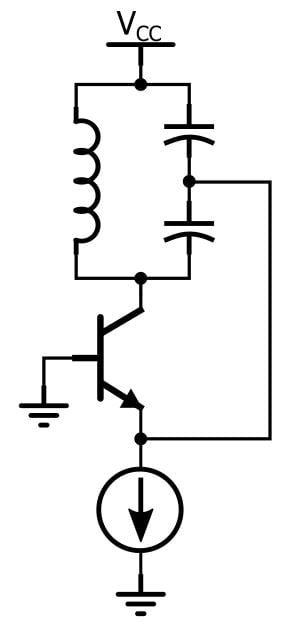
A quartz crystal is a crystal, not an oscillator. To produce oscillation, the crystal must be incorporated into a circuit that has the typical characteristics exhibited by oscillator circuits, namely, amplification and feedback. If you look at classic oscillator topologies such as the Colpitts or Hartley, you’ll see an amplifier (such as a BJT), an LC tank circuit (to provide resonance), and a feedback connection—in a Colpitts oscillator, for example, the feedback goes from a node between two capacitors in the tank circuit to the emitter of a BJT:
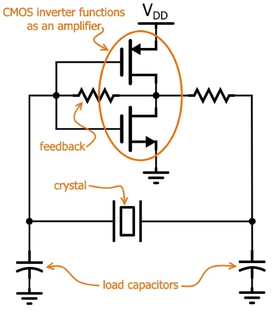
The general idea is the same with quartz-based oscillators, because a quartz crystal is essentially a very-high-performance resonant element. The Pierce (or Pierce–Gate) oscillator is a common topology used for producing digital oscillation; it looks like this:
You could spend quite a long time trying to thoroughly analyze and understand all the details of this seemingly simple circuit. If you want to go deeper into the Pierce topology and into crystal-based oscillation in general, I think that the article "Pierce-Gate Crystal Oscillator, an introduction" (written for Microwave Product Digest) would be a good place to start.
Conclusion
I hope that you now have a clearer idea of 1) what a quartz crystal is in the context of electronics and 2) how the characteristics of a quartz crystal can lead to oscillation when combined with a properly designed circuit.
For information on alternatives to quartz-based oscillation, take a look at my article on oscillator options for microcontrollers and my news piece on a MEMS oscillator that may offer performance far superior to that of a crystal.


Thank you, really enjoyed this article!
What I’d like to know is how quartz crystals can be mass-produced and at the same time cut so accurately, to eg 5 or 6 or more significant figures?