 Facebook
 Google
 GitHub
 Linkedin
How to Measure the Drive Level of a Quartz Crystal
Learn why the drive level of your quartz crystal oscillator is important and several methods for how to measure it.
Drive level refers to the amount of power dissipated in a crystal. A crystal has mechanical vibrations. A higher drive level can increase the amplitude of the vibrations to an unacceptable level and cause undesired effects. To limit these vibrations, the power dissipated in the crystal should not exceed the value specified by the manufacturer.
Typical drive level values are in the range of 100 μW. With smaller surface mount crystals, the rated drive level can be even smaller (about 10 μW).
In this article, we’ll take a look at the test setups and the related equations that can be used to measure the crystal power level.
Drive Level Dependency
Increasing the drive level can lead to an increase in the motional resistance and frequency of the crystal. This effect, commonly referred to as drive level dependency (DLD), is illustrated in Figure 1.
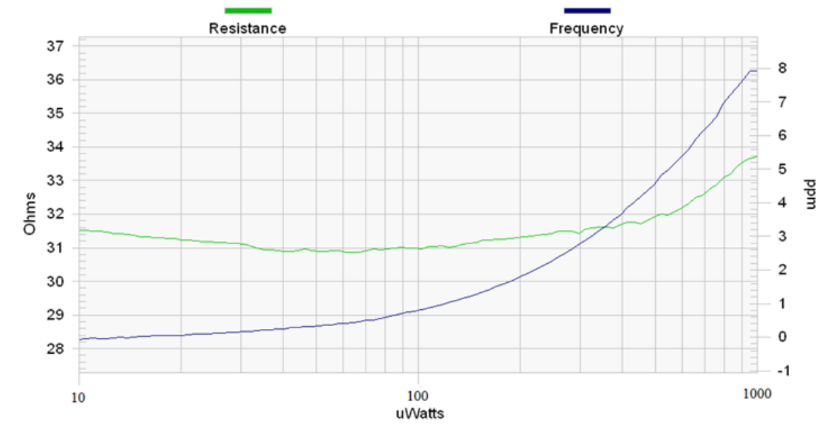
Figure 1. Crystal motional resistance and frequency versus drive level. Image courtesy of Renesas.
Very low drive levels can also increase the series resistance of a crystal to a value that makes the oscillator unable to start up. Due to this effect, a given crystal will sometimes start up successfully and fail at other times.
These crystals are sometimes referred to as “sleeping crystals”. Interestingly, the crystals that have been inactive for some time can also exhibit a large series resistance well above the rated value. This can also lead to a crystal that is occasionally unable to start up. The inactivity period that can cause this effect can be hours to weeks depending on the crystal quality.
Overdriving Can Cause Serious Damage
Exceeding the stated drive level can lead to several undesired effects. It can shorten the device lifetime, cause oscillation frequency fluctuations, and degrade the stability. Figure 2 shows how exceeding the maximum drive level can change the frequency versus temperature response of a crystal.

Figure 2. The effect of exceeding max drive level on a crystal's frequency and temperature response. Image courtesy of Raltron.
In this example, crystals rated at 10 μW are overdriven at 500 μW. Instead of having smooth frequency versus temperature curves, we observe an erratic temperature response. At significantly higher power levels (e.g., at 10x the rated value), overdriving can cause irreversible damage to the crystal.
Measuring Drive Level Using a Current Probe
Since the crystal drive level cannot be measured directly, we need to measure a circuit quantity, such as a voltage or current, and use the crystal electrical model to approximate its power level. The equivalent electrical circuit for a crystal is shown in Figure 3.

Figure 3. The equivalent electrical circuit for a crystal. Image courtesy of STMicroelectronics.
We only need to find the effective resistance of this network at resonance and measure the crystal current to calculate the drive level. The crystal equivalent series resistance (ESR) at load capacitance CL is given by:
\[ESR = R_m \left(1 + \frac{C_0}{C_L}\right)^2\]
The drive level can be obtained as:
\[DL = ESR \times {I_{Q,~RMS}}^2\]
Equation 1
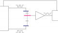
where IQ, RMS denotes the RMS current flowing through the crystal. As shown in Figure 4, a current probe can be used to measure the crystal current.
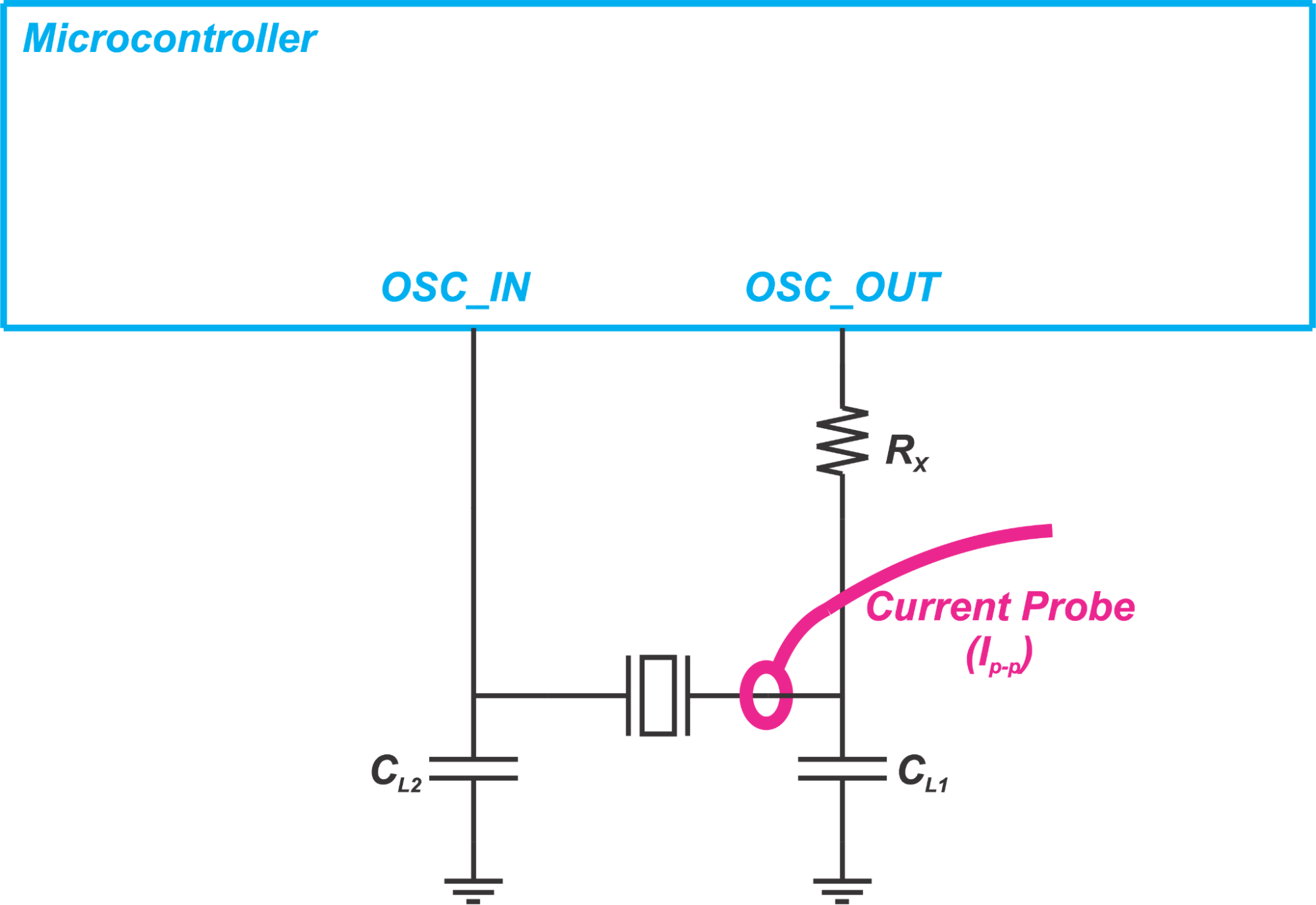
Figure 4. Using a current probe to measure crystal current
Figure 5 shows applying this technique in practice.
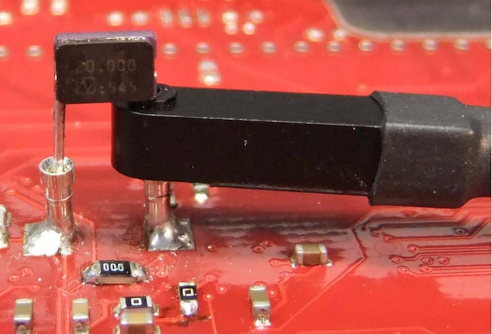
Figure 5. A PCB with a current probe measuring crystal current. Image courtesy of Infineon.
The crystal current is usually either sinusoidal or saw-tooth. Figure 6 shows an example where the current waveform is approximately sinusoidal.
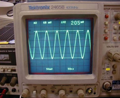
Figure 6. The current flowing through the crystal. Image courtesy of Epson.
With a sinusoidal waveform, we can apply the following equation to find the RMS value from the peak-to-peak value (IQ, p-p):
\[I_{Q,~RMS} = \frac{I_{Q,~p-p}}{2\sqrt{2}}\]
With a saw-tooth waveform, the RMS value is given by:
\[I_{Q,~RMS} = \frac{I_{Q,~p-p}}{2\sqrt{3}}\]
Depending on the waveform type, one of these two equations should be used to find the RMS value from the peak-to-peak value. Then, we can substitute the RMS current in Equation 1 and calculate the drive level.
Inserting a Series Resistor to Measure the Crystal Current
If a current probe is not available, we can temporarily place a small resistor in series with the crystal and use a differential probe to measure the voltage across the resistor.
Having the resistor value and the voltage drop, we can find the crystal current. This is shown in Figure 7.
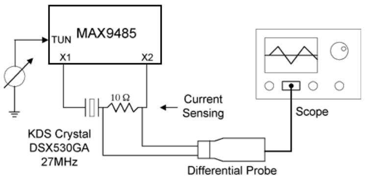
Figure 7. Representation of a setup to find the crystal current. Image courtesy of Maxim Integrated.
To make sure that the resistor is small enough and does not contribute a significant measurement error, the Maxim Integrated application note suggests that we increase the resistor value slightly and verify that the sensed current is barely changed. In this example, the resistor value is changed from 10 Ω to 20 Ω.
Finding the Drive Level by Measuring the Amplifier Input Voltage
In this case, the RMS voltage at the input of the amplifier (VIN, RMS) is measured through a low-capacitance oscilloscope probe (less than 1 pF).
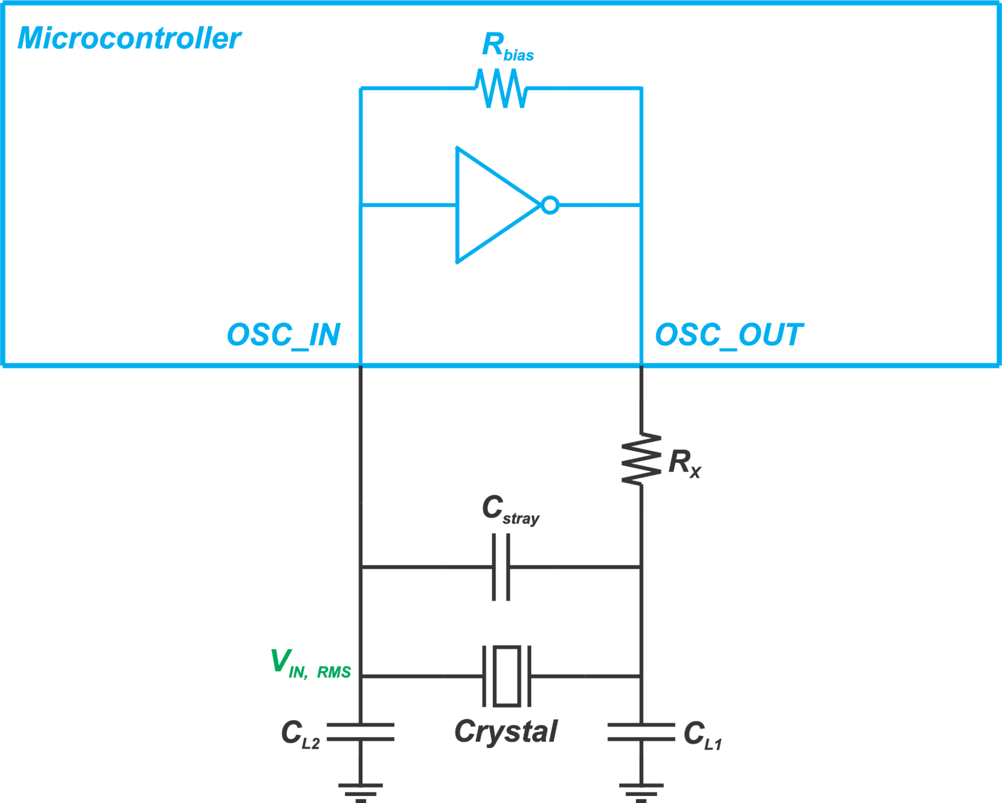
Figure 8. Using an oscilloscope probe to measure the RMS voltage at the input of the amplifier
Having VIN, RMS, we can calculate the current flowing through CL2 as:
\[I_{RMS} = (2\pi fC_{L2})V_{IN,~RMS}\]
To be more accurate, we can also include the parasitic effects and substitute CL2 with Ctotal given below:
\[C_{total} = C_{L2} + \frac{C_s}{2} + C_{Probe}\]
where CStray and CProbe are the stray and probe capacitances, respectively. The current that flows into the amplifier input is much smaller than the current that flows through this total capacitance. Hence, we can assume that the total current flowing through the crystal is equal to the current flowing through Ctotal. This gives us the drive level as:
\[DL = ESR \times {I_{RMS}}^2 = ESR \times {\left(2\pi fC_{total}V_{IN,~RMS}\right)}^2\]
Assuming that the voltage waveform at the amplifier input is sinusoidal, we can use
\[V_{IN,~RMS} = \frac{V_{IN,~p-p}}{2\sqrt{2}}\]
and calculate the drive level as:
\[DL = ESR \times {(\pi fC_{total})}^2 \times \frac{{V_{p-p}}^2}{2}\]
Finding the Drive Level by Measuring the Crystal Voltage
For the sake of thoroughness, I would like to mention another equation that is sometimes used to calculate the drive level. This method is based on measuring the voltage across the crystal.
We know that, at resonance, the magnitude of the impedance of the motional branch in the crystal model (the series combination of Lm, Cm, and Rm) is equal to the magnitude of the impedance of the parallel combination of CL and C0. Hence, we can approximate the RMS current flowing through the motional arm by:
\[I_{Motional~Arm,~RMS} = V_{Crystal,~RMS} \times (2\pi f(C_L + C_0))\]
where VCrystal, RMS denotes the measured RMS voltage across the crystal. The drive level can be found by:
\[DL = R_m \times {(2\pi f(C_L + C_0))}^2 \times {V_{Crystal,~RMS}}^2\]
Assuming that the crystal voltage is a sinusoidal waveform with a peak value of Vp, we can substitute VCrystal, RMS with \[\frac{V_p}{\sqrt{2}}\] and obtain the following equation:
\[DL = 2 \times R_m \times {(\pi f(C_L + C_0)V_p)}^2\]
The CC26xx and CC13xx family of wireless MCUs from TI provide functions that return the amplitude of the crystal oscillation voltage in mV. Having the oscillation amplitude, we can easily apply the above equation and find the crystal drive level during operation. If the rated drive level is exceeded, we need to re-examine our design to avoid any crystal reliability issues.
Adding a Series Resistor to Limit the Drive Level
If the drive level is not within the expected range, a resistor can be added to limit the current and consequently the drive level of the crystal (Rx in Figure 4). After Rx is chosen based on the target drive level, we should ensure that the frequency is within the expected accuracy.
Moreover, the oscillator negative resistance should be examined to make sure that it provides sufficient margin. A large Rx can prevent the oscillator from oscillating.
To see a complete list of my articles, please visit this page.
Related Content


Hi! Thank you for this article. Can you please mention the sources you have used for derivation of formulas mentioned in this article? Any papers or specification sheets would be helpful. Thank you.