Facebook
 Google
 GitHub
 Linkedin
Multimeters
Seeing as how a common meter movement can be made to function as a voltmeter, ammeter, or ohmmeter simply by connecting it to different external resistor networks, it should make sense that a multi-purpose meter (“multimeter”) could be designed in one unit with the appropriate switch(es) and resistors.
For general purpose electronics work, the multimeter reigns supreme as the instrument of choice. No other device is able to do so much with so little an investment in parts and elegant simplicity of operation. As with most things in the world of electronics, the advent of solid-state components like transistors has revolutionized the way things are done, and multimeter design is no exception to this rule. However, in keeping with this chapter’s emphasis on analog (“old-fashioned”) meter technology, I’ll show you a few pre-transistor meters.
Analog Multimeter

The unit shown above is typical of a handheld analog multimeter, with ranges for voltage, current, and resistance measurement. Note the many scales on the face of the meter movement for the different ranges and functions selectable by the rotary switch. The wires for connecting this instrument to a circuit (the “test leads” or multimeter leads) are plugged into the two copper jacks (socket holes) at the bottom-center of the meter face marked “- TEST +”, black and red.

This multimeter (Barnett brand) takes a slightly different design approach than the previous unit. Note how the rotary selector switch has fewer positions than the previous meter, but also how there are many more jacks into which the test leads may be plugged into. Each one of those jacks is labeled with a number indicating the respective full-scale range of the meter.
Digital Multimeter

Lastly, here is a picture of a digital multimeter. Note that the familiar meter movement has been replaced by a blank, gray-colored display screen. When powered, numerical digits appear in that screen area, depicting the amount of voltage, current, or resistance being measured. This particular brand and model of digital meter has a rotary selector switch and four jacks into which test leads can be plugged. Two leads—one red and one black—are shown plugged into the meter.
A close examination of this meter will reveal one “common” jack for the black test lead and three others for the red test lead. The jack into which the red lead is shown inserted is labeled for voltage and resistance measurement, while the other two jacks are labeled for current (A, mA, and µA) measurement. This is a wise design feature of the multimeter, requiring the user to move a test lead plug from one jack to another in order to switch from the voltage measurement to the current measurement function.
It would be hazardous to have the meter set in current measurement mode while connected across a significant source of voltage because of the low input resistance, and making it necessary to move a test lead plug rather than just flip the selector switch to a different position helps ensure that the meter doesn’t get set to measure current unintentionally.
Note that the selector switch still has different positions for voltage and current measurement, so in order for the user to switch between these two modes of measurement they must switch the position of the red test lead and move the selector switch to a different position.
Also note that neither the selector switch nor the jacks are labeled with measurement ranges. In other words, there are no “100 volt” or “10 volt” or “1 volt” ranges (or any equivalent range steps) on this meter. Rather, this meter is “autoranging,” meaning that it automatically picks the appropriate range for the quantity being measured. Autoranging is a feature only found on digital meters, but not all digital meters.
No two models of multimeters are designed to operate exactly the same, even if they’re manufactured by the same company. In order to fully understand the operation of any multimeter, the owner’s manual must be consulted.
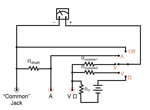
Here is a schematic for a simple analog volt/ammeter:

In the switch’s three lower (most counter-clockwise) positions, the meter movement is connected to the Common and V jacks through one of three different series range resistors (Rmultiplier1 through Rmultiplier3), and so acts as a voltmeter. In the fourth position, the meter movement is connected in parallel with the shunt resistor, and so acts as an ammeter for any current entering the common jack and exiting the A jack.
In the last (furthest clockwise) position, the meter movement is disconnected from either red jack, but short-circuited through the switch. This short-circuiting creates a dampening effect on the needle, guarding against mechanical shock damage when the meter is handled and moved.
If an ohmmeter function is desired in this multimeter design, it may be substituted for one of the three voltage ranges as such:
With all three fundamental functions available, this multimeter may also be known as a volt-ohm-milliammeter.
Obtaining a reading from an analog multimeter when there is a multitude of ranges and only one meter movement may seem daunting to the new technician. On an analog multimeter, the meter movement is marked with several scales, each one useful for at least one range setting. Here is a close-up photograph of the scale from the Barnett multimeter shown earlier in this section:

Note that there are three types of scales on this meter face: a green scale for resistance at the top, a set of black scales for DC voltage and current in the middle, and a set of blue scales for AC voltage and current at the bottom. Both the DC and AC scales have three sub-scales, one ranging 0 to 2.5, one ranging 0 to 5, and one ranging 0 to 10. The meter operator must choose whichever scale best matches the range switch and plug settings in order to properly interpret the meter’s indication.
This particular multimeter has several basic voltage measurement ranges: 2.5 volts, 10 volts, 50 volts, 250 volts, 500 volts, and 1000 volts. With the use of the voltage range extender unit at the top of the multimeter, voltages up to 5000 volts can be measured. Suppose the meter operator chose to switch the meter into the “volt” function and plug the red test lead into the 10-volt jack.
To interpret the needle’s position, he or she would have to read the scale ending with the number “10”. If they moved the red test plug into the 250 volt jack, however, they would read the meter indication on the scale ending with “2.5”, multiplying the direct indication by a factor of 100 in order to find what the measured voltage was.
If current is measured with this meter, another jack is chosen for the red plug to be inserted into and the range is selected via a rotary switch. This close-up photograph shows the switch set to the 2.5 mA position:

Note how all current ranges are power-of-ten multiples of the three scale ranges shown on the meter face: 2.5, 5, and 10. In some range settings, such as the 2.5 mA for example, the meter indication may be read directly on the 0 to 2.5 scale. For other range settings (250 µA, 50 mA, 100 mA, and 500 mA), the meter indication must be read off the appropriate scale and then multiplied by either 10 or 100 to obtain the real figure.
The highest current range available on this meter is obtained with the rotary switch in the 2.5/10 amp position. The distinction between 2.5 amps and 10 amps is made by the red test plug position: a special “10 amp” jack next to the regular current-measuring jack provides an alternative plug setting to select the higher range.
Resistance in ohms, of course, is read by a nonlinear scale at the top of the meter face. It is “backward,” just like all battery-operated analog ohmmeters, with zero at the right-hand side of the face and infinity at the left-hand side. There is only one jack provided on this particular multimeter for “ohms,” so different resistance-measuring ranges must be selected by the rotary switch.
Notice on the switch how five different “multiplier” settings are provided for measuring resistance: Rx1, Rx10, Rx100, Rx1000, and Rx10000. Just as you might suspect, the meter indication is given by multiplying whatever needle position is shown on the meter face by the power-of-ten multiplying factor set by the rotary switch.
RELATED WORKSHEETS: