 Facebook
 Google
 GitHub
 Linkedin
Ohmmeter Design
Though mechanical ohmmeter (resistance meter) designs are rarely used today, having largely been superseded by digital instruments, their operation is nonetheless intriguing and worthy of study.
Ohmmeter’s Purpose
The purpose of an ohmmeter, of course, is to measure the resistance placed between its leads. This resistance reading is indicated through a mechanical meter movement which operates on electric current. The ohmmeter must then have an internal source of voltage to create the necessary current to operate the movement, and also have appropriate ranging resistors to allow just the right amount of current through the movement at any given resistance.
How Does an Ohmmeter Work?
Starting with a simple movement and battery circuit, let’s see how it would function as an ohmmeter:
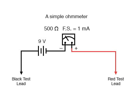
When there is infinite resistance (no continuity between test leads), there is zero current through the meter movement, and the needle points toward the far left of the scale. In this regard, the ohmmeter indication is “backwards” because maximum indication (infinity) is on the left of the scale, while voltage and current meters have zero at the left of their scales.
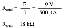
If the test leads of this ohmmeter are directly shorted together (measuring zero Ω), the meter movement will have a maximum amount of current through it, limited only by the battery voltage and the movement’s internal resistance:
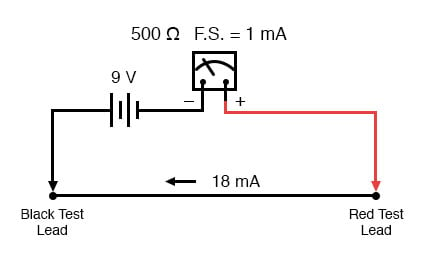
With 9 volts of battery potential and only 500 Ω of movement resistance, our circuit current will be 18 mA, which is far beyond the full-scale rating of the movement. Such an excess of current will likely damage the meter.
Not only that, but having such a condition limits the usefulness of the device. If full left-of-scale on the meter face represents an infinite amount of resistance, then full right-of-scale should represent zero. Currently, our design “pegs” the meter movement hard to the right when zero resistance is attached between the leads. We need a way to make it so that the movement just registers full-scale when the test leads are shorted together. This is accomplished by adding a series resistance to the meter’s circuit:

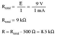
To determine the proper value for R, we calculate the total circuit resistance needed to limit current to 1 mA (full-scale deflection on the movement) with 9 volts of potential from the battery, then subtract the movement’s internal resistance from that figure:
Now that the right value for R has been calculated, we’re still left with a problem of meter range. On the left side of the scale we have “infinity” and on the right side we have zero. Besides being “backwards” from the scales of voltmeters and ammeters, this scale is strange because it goes from nothing to everything, rather than from nothing to a finite value (such as 10 volts, 1 amp, etc.).
One might pause to wonder, “what does middle-of-scale represent? What figure lies exactly between zero and infinity?” Infinity is more than just a very big amount: it is an incalculable quantity, larger than any definite number ever could be. If half-scale indication on any other type of meter represents 1/2 of the full-scale range value, then what is half of infinity on an ohmmeter scale?
Ohmmeter’s Logarithmic Scale
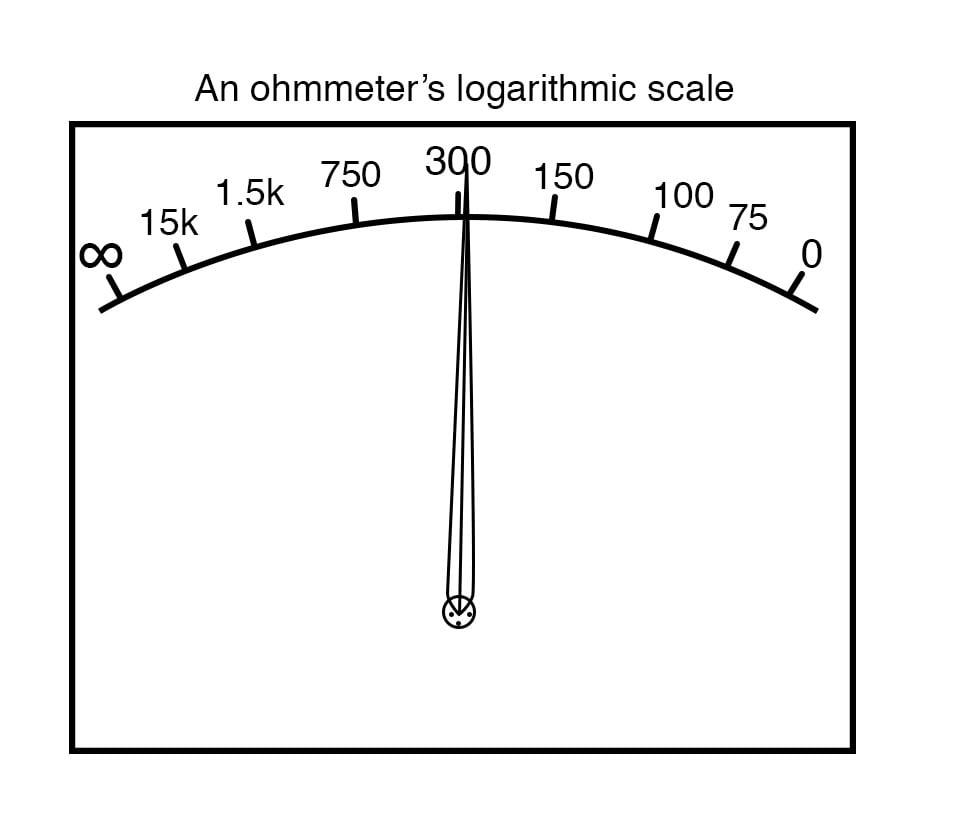
The answer to this paradox is a nonlinear scale. Simply put, the scale of an ohmmeter does not smoothly progress from zero to infinity as the needle sweeps from right to left. Rather, the scale starts out “expanded” at the right-hand side, with the successive resistance values growing closer and closer to each other toward the left side of the scale:
Infinity cannot be approached in a linear (even) fashion, because the scale would never get there! With a nonlinear scale, the amount of resistance spanned for any given distance on the scale increases as the scale progresses toward infinity, making infinity an attainable goal.
We still have a question of range for our ohmmeter, though. What value of resistance between the test leads will cause exactly 1/2 scale deflection of the needle? If we know that the movement has a full-scale rating of 1 mA, then 0.5 mA (500 µA) must be the value needed for half-scale deflection. Following our design with the 9 volt battery as a source we get:
With an internal movement resistance of 500 Ω and a series range resistor of 8.5 kΩ, this leaves 9 kΩ for an external (lead-to-lead) test resistance at 1/2 scale. In other words, the test resistance giving 1/2 scale deflection in an ohmmeter is equal in value to the (internal) series total resistance of the meter circuit.
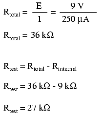
Using Ohm’s Law a few more times, we can determine the test resistance value for 1/4 and 3/4 scale deflection as well:
1/4 scale deflection (0.25 mA of meter current):
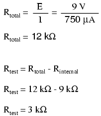
3/4 scale deflection (0.75 mA of meter current):
So, the scale for this ohmmeter looks something like this:
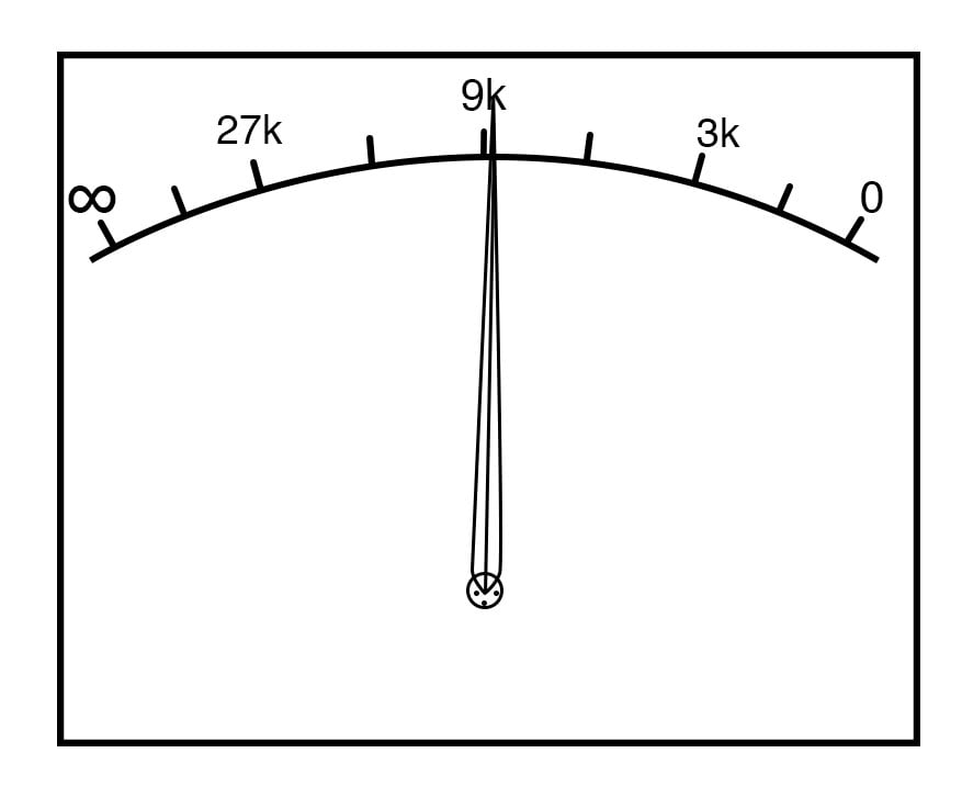
One major problem with this design is its reliance upon a stable battery voltage for accurate resistance reading. If the battery voltage decreases (as all chemical batteries do with age and use), the ohmmeter scale will lose accuracy. With the series range resistor at a constant value of 8.5 kΩ and the battery voltage decreasing, the meter will no longer deflect full-scale to the right when the test leads are shorted together (0 Ω). Likewise, a test resistance of 9 kΩ will fail to deflect the needle to exactly 1/2 scale with a lesser battery voltage.
There are design techniques used to compensate for varying battery voltage, but they do not completely take care of the problem and are to be considered approximations at best. For this reason, and for the fact of the nonlinear scale, this type of ohmmeter is never considered to be a precision instrument.
One final caveat needs to be mentioned with regard to ohmmeters: they only function correctly when measuring resistance that is not being powered by a voltage or current source. In other words, you cannot measure resistance with an ohmmeter on a “live” circuit! The reason for this is simple: the ohmmeter’s accurate indication depends on the only source of voltage being its internal battery. The presence of any voltage across the component to be measured will interfere with the ohmmeter’s operation. If the voltage is large enough, it may even damage the ohmmeter.
REVIEW:
- Ohmmeters contain internal sources of voltage to supply power in taking resistance measurements.
- An analog ohmmeter scale is “backwards” from that of a voltmeter or ammeter, the movement needle reading zero resistance at full-scale and infinite resistance at rest.
- Analog ohmmeters also have nonlinear scales, “expanded” at the low end of the scale and “compressed” at the high end to be able to span from zero to infinite resistance.
- Analog ohmmeters are not precision instruments.
- Ohmmeters should never be connected to an energized circuit (that is, a circuit with its own source of voltage). Any voltage applied to the test leads of an ohmmeter will invalidate its reading.
RELATED WORKSHEETS:


