Facebook
 Google
 GitHub
 Linkedin
High Voltage Ohmmeters
Most ohmmeters of the design shown in the previous section utilize a battery of relatively low voltage, usually nine volts or less. This is perfectly adequate for measuring resistances under several mega-ohms (MΩ), but when extremely high resistances need to be measured, a 9-volt battery is insufficient for generating enough current to actuate an electromechanical meter movement.
Also, as discussed in an earlier chapter, resistance is not always a stable (linear) quantity. This is especially true of non-metals. Recall the graph of current overvoltage for a small air gap (less than an inch):

While this is an extreme example of nonlinear conduction, other substances exhibit similar insulating/conducting properties when exposed to high voltages. Obviously, an ohmmeter using a low-voltage battery as a source of power cannot measure resistance at the ionization potential of a gas, or at the breakdown voltage of an insulator. If such resistance values need to be measured, nothing but a high-voltage ohmmeter will suffice.
Simple High-Voltage Ohmmeter
The most direct method of high-voltage resistance measurement involves simply substituting a higher voltage battery in the same basic design of ohmmeter investigated earlier:

Knowing, however, that the resistance of some materials tends to change with applied voltage, it would be advantageous to be able to adjust the voltage of this ohmmeter to obtain resistance measurements under different conditions:

Unfortunately, this would create a calibration problem for the meter. If the meter movement deflects full-scale with a certain amount of current through it, the full-scale range of the meter in ohms would change as the source voltage changed. Imagine connecting a stable resistance across the test leads of this ohmmeter while varying the source voltage: as the voltage is increased, there will be more current through the meter movement, hence a greater amount of deflection. What we really need is a meter movement that will produce a consistent, stable deflection for any stable resistance value measured, regardless of the applied voltage.
Megger Meter
Accomplishing this design goal requires a special meter movement, one that is peculiar to megohmmeters, or meggers, as these instruments are known.

The numbered, rectangular blocks in the above illustration are cross-sectional representations of wire coils. These three coils all move with the needle mechanism. There is no spring mechanism to return the needle to a set position. When the movement is unpowered, the needle will randomly “float.” The coils are electrically connected like this:

With infinite resistance between the test leads (open circuit), there will be no current through coil 1, only through coils 2 and 3. When energized, these coils try to center themselves in the gap between the two magnet poles, driving the needle fully to the right of the scale where it points to “infinity.”

Any current through coil 1 (through a measured resistance connected between the test leads) tends to drive the needle to the left of scale, back to zero. The internal resistor values of the meter movement are calibrated so that when the test leads are shorted together, the needle deflects exactly to the 0 Ω position.
Because any variations in battery voltage will affect the torque generated by both sets of coils (coils 2 and 3, which drive the needle to the right, and coil 1, which drives the needle to the left), those variations will have no effect of the calibration of the movement. In other words, the accuracy of this ohmmeter movement is unaffected by battery voltage: a given amount of measured resistance will produce a certain needle deflection, no matter how much or little battery voltage is present.
The only effect that a variation in voltage will have on meter indication is the degree to which the measured resistance changes with applied voltage. So, if we were to use a megger to measure the resistance of a gas-discharge lamp, it would read very high resistance (needle to the far right of the scale) for low voltages and low resistance (needle moves to the left of the scale) for high voltages. This is precisely what we expect from a good high-voltage ohmmeter: to provide an accurate indication of subject resistance under different circumstances.
For maximum safety, most meggers are equipped with hand-crank generators for producing the high DC voltage (up to 1000 volts). If the operator of the meter receives a shock from the high voltage, the condition will be self-correcting, as he or she will naturally stop cranking the generator! Sometimes a “slip clutch” is used to stabilize generator speed under different cranking conditions, so as to provide a fairly stable voltage whether it is cranked fast or slow. Multiple voltage output levels from the generator are available by the setting of a selector switch.
A simple hand-crank megger is shown in this photograph:

Some meggers are battery-powered to provide greater precision in output voltage. For safety reasons these meggers are activated by a momentary-contact pushbutton switch, so the switch cannot be left in the “on” position and pose a significant shock hazard to the meter operator.
Real Meggers
Real meggers are equipped with three connection terminals, labeled Line, Earth, and Guard. The schematic is quite similar to the simplified version shown earlier:
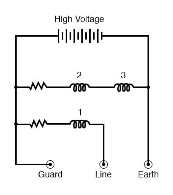
Resistance is measured between the Line and Earth terminals, where current will travel through coil 1. The “Guard” terminal is provided for special testing situations where one resistance must be isolated from another. Take for instance this scenario where the insulation resistance is to be tested in a two-wire cable:

To measure insulation resistance from a conductor to the outside of the cable, we need to connect the “Line” lead of the megger to one of the conductors and connect the “Earth” lead of the megger to a wire wrapped around the sheath of the cable:

In this configuration, the megger should read the resistance between one conductor and the outside sheath. Or will it? If we draw a schematic diagram showing all insulation resistances as resistor symbols, what we have looks like this:
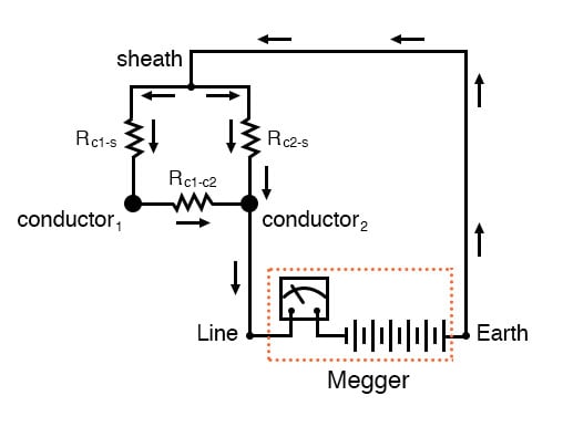
Rather than just measure the resistance of the second conductor to the sheath (Rc2-s), what we’ll actually measure is the resistance in parallel with the series combination of conductor-to-conductor resistance (Rc1-c2) and the first conductor to the sheath (Rc1-s). If we don’t care about this fact, we can proceed with the test as configured. If we desire to measure only the resistance between the second conductor and the sheath (Rc2-s), then we need to use the megger’s “Guard” terminal:

Now the circuit schematic looks like this:

Connecting the “Guard” terminal to the first conductor places the two conductors at almost equal potential. With little or no voltage between them, the insulation resistance is nearly infinite, and thus there will be no current between the two conductors. Consequently, the megger’s resistance indication will be based exclusively on the current through the second conductor’s insulation, through the cable sheath, and to the wire wrapped around, not the current leaking through the first conductor’s insulation.
Meggers are field instruments: that is, they are designed to be portable and operated by a technician on the job site with as much ease as a regular ohmmeter. They are very useful for checking high-resistance “short” failures between wires caused by wet or degraded insulation. Because they utilize such high voltages, they are not as affected by stray voltages (voltages less than 1 volt produced by electrochemical reactions between conductors, or “induced” by neighboring magnetic fields) as ordinary ohmmeters.
Hi-Pot Testers
For a more thorough test of wire insulation, another high-voltage ohmmeter commonly called a hi-pot tester is used. These specialized instruments produce voltages in excess of 1 kV, and may be used for testing the insulating effectiveness of oil, ceramic insulators, and even the integrity of other high-voltage instruments. Because they are capable of producing such high voltages, they must be operated with the utmost care, and only by trained personnel.
It should be noted that hi-pot testers and even meggers (in certain conditions) are capable of damaging wire insulation if incorrectly used. Once an insulating material has been subjected to breakdown by the application of an excessive voltage, its ability to electrically insulate will be compromised. Again, these instruments are to be used only by trained personnel.
RELATED WORKSHEETS: