Facebook
 Google
 GitHub
 Linkedin
Why Your PCB Design Review Process is Obsolete and How to Fix It
Sending static PDFs and Gerbers for feedback is killing your project timelines and leading to costly PCB rework. Learn how to break down engineering silos and modernize your PCB design reviews.
Hardware development cycles are accelerating. A 2024 survey by Protolabs indicates that the majority of organizations are pushing to develop new products faster in order to sustain a competitive edge. Yet, as engineering organizations scale their velocity across distributed teams and more complex projects, they regularly encounter a paradox: they require the speed of a startup but the structured control of an enterprise.
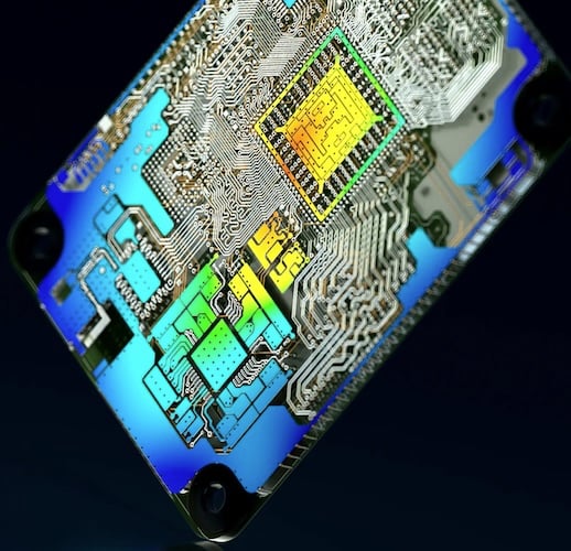
Modern PCB designs can benefit from modern design review processes.
This conflict is especially apparent during the printed circuit board design review phase. Many electronics development teams are hindered by administrative overhead, which diverts focus from active design and innovation. The core issue is not that design reviews are obsolete, but that the traditional, disconnected model of conducting them simply cannot scale with modern hardware complexity.
The Breakdown of Legacy Review Models
In many organizations, engineers continue to operate in functional silos: electrical teams in their ECAD environments, mechanical teams in their MCAD, software developers in their IDEs, and sourcing specialists in their spreadsheets. Because these disciplines speak different languages and operate on independent timelines, coordination depends almost entirely on manual human effort.
The legacy review process relies heavily on exporting file packages. PCB designers generate massive ZIP archives of static PDFs, standard Gerber files, and STEP models, then email them to various stakeholders. Feedback is collected asynchronously in disconnected spreadsheets or generic project management tickets, all of which quickly drift out of sync with the actual design files.
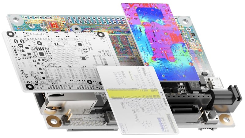
Unifying electrical, mechanical, software, and sourcing can improve design and development productivity.
This system, while considered methodical on paper pre-Industry 4.0, incurs significant risk. When feedback loops take days or weeks to close, decisions are delayed, and critical errors bypass the review phase. These errors then surface downstream, where fundamental quality-engineering principles dictate that they are exponentially more expensive to fix. Industry research from Bain & Company confirms this creeping inefficiency, noting that engineers in aerospace and defense firms often lose significant hours to rework and administrative tasks, devoting barely half of their time to active design work.
So, what should be checked during a PCB design review before releasing it to fabrication?
Checks and Reviews Before Fabrication
Preventing downstream failures requires a comprehensive review that must interrogate the design across multiple domains. Before releasing a board to fabrication, a structured workflow should include checks for the following:
- Electrical integrity: Verifying trace widths for current-carrying capacity, checking impedance profiles for high-speed signals, and guaranteeing appropriate isolation clearances for high-voltage nets
- Mechanical fit: Confirming 3D enclosure clearances, connector placements, and mounting hole alignments to ensure the populated PCB physically fits into its housing
- Manufacturability (DfM): Validating test point accessibility, assessing thermal relief geometries to prevent tombstoning, and confirming that annular rings and drill sizes meet the fabricator's capabilities
- Supply chain viability: Scrutinizing the BOM one final time before release to catch any components that may have transitioned to EOL or NRND status during the layout phase
The Limits of Automated Design Rule Check
It is a dangerous misconception that a clean design rule check (DRC) equates to a production-ready board. In truth, while automated DRC is vital for enforcing basic dimensional and electrical constraints, it fundamentally lacks human context.
But what are the most common PCB design errors caught in a formal design review that DRC misses?
- Functional intent: DRC cannot determine whether a layout engineer swapped the RX and TX lines on a UART interface or whether a decoupling capacitor is placed too far from an IC’s power pin to filter noise effectively.
- Component obsolescence: ECAD constraints fail to flag when a selected component is out of stock globally or nearing its end of life.
- Advanced mechanical conflicts: Basic 2D DRC often misses complex 3D mechanical conflicts, such as an electrolytic capacitor colliding with an unmapped plastic enclosure rib.
- Testability and debugging: Automated rules rarely catch inaccessible test points or missing silkscreen labels, which can frustrate technicians during board bring-up.
A Better Technical Workflow: Context-Aware Collaboration
To fix the review bottleneck, hardware teams need to adopt a structured, collaborative, and context-aware process. Instead of treating each discipline as a separate process with occasional check-ins, a modern platform integrates all disciplines into a single continuous workflow. Shared data replaces file transfers, and visibility into design changes becomes automatic.
The following table illustrates the shift from a legacy approach to a modern co-creation model:
| Capability | Legacy Collaboration | Modern Co-Creation |
| Workspace | Teams work in functional silos | Cross-functional teams work in a shared space |
| Data Management | Data is transferred between roles and tools via files | Data is shared in real time within one environment |
| Coordination | Requires formal meetings, emails, and manual handoffs | Built into the platform, live and direct |
| Feedback Loop | Takes days or weeks; changes cause downstream surprises | Happens constantly in context; changes are immediately visible |
| Alignment | Reactive and periodic | Automatic and integrated |
Breaking Down License Barriers
Accessibility is a major point of friction in legacy workflows. Traditionally, reviewing a native layout required an expensive, localized software license. Because non-electrical stakeholders—such as mechanical engineers, procurement specialists, and manufacturing test engineers—rarely possess full ECAD authoring licenses, they are forced to rely on exported static files or generic viewer applications that strip away critical metadata.
So, which PCB collaboration platforms let stakeholders review and annotate a design without a full ECAD license?
Modern cloud architectures allow for decoupling the review environment from the authoring tool. One example is Altium Agile Teams, which securely manages stakeholders using role-based team permissions and guest collaborator access. This architecture renders the native design data directly inside a standard web browser, allowing procurement managers, mechanical engineers, and external clients to view and interact with the design without installing specialized software.
By removing the license barrier, stakeholders can inspect schematic cross-probing, interrogate specific layers, and independently verify 3D component models. In a pragmatic deployment, a global access license permits up to 250 project collaborators to participate simultaneously from anywhere in the world, without requiring them to hold individual ECAD authoring licenses.
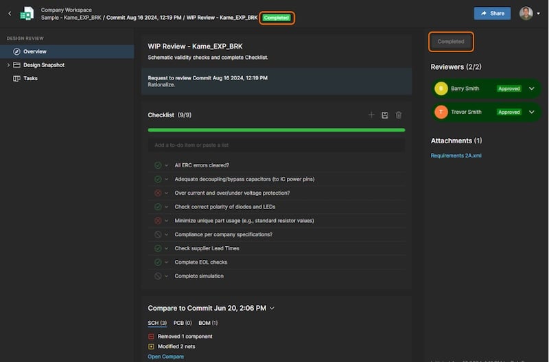
A browser‑based design review with checklist status, reviewer approvals, and change comparison in Altium.
Executing a Distributed, Structured Review
Managing reviews across multiple time zones allows for a shift away from synchronous meetings. Attempting to coordinate a live review session with hardware engineers in North America, a manufacturing facility in Asia, and software developers in Europe often results in delayed approvals and rushed checks. Mitigating this risk requires shifting toward asynchronous, distributed design reviews.
So, how do you run a structured PCB design review with a distributed team using a cloud platform?
Instead of relying on ad-hoc emails, engineering teams must anchor their reviews in a central, version-controlled environment. Integrating custom checklists directly into the platform standardizes best practices and eliminates the process variations that cause rework. For instance, a mandatory checklist can ensure that high-speed impedance profiles are verified before the team evaluates test point accessibility, ensuring a logical progression of checks.
The review environment should also feature a live connection to component supply chain data. This enables cross-functional collaboration, allowing procurement teams to co-design with PCB designers in a dynamic cloud portal and proactively catch pricing anomalies or allocation limits, rather than reacting to them late in the cycle.
Keeping Feedback in Context
To avoid the confusion of scattered emails, feedback must be tied directly to the design data. In legacy processes, a reviewer might take a screenshot of a specific layer, draw a red circle around a problematic via, and attach it to a generic project management ticket. By the time the layout engineer addresses the ticket, the board routing may have evolved, rendering the screenshot obsolete and the requested change ambiguous.
So, how do you add review comments and markups to a PCB layout so they are visible to the whole team?
Using a connected cloud environment fundamentally resolves this disconnect. Reviewers can click on a specific trace, component, or schematic symbol directly in their browser and leave a contextual comment at those exact coordinates, which generates a task directly within the design documents, bypassing intermediate documents entirely.
Because the platform maintains a common digital thread, these web-based comments synchronize instantly with the layout engineer's native ECAD software. When the designer opens their local layout workspace, the markup appears exactly where the reviewer placed it. All requested changes are tracked, and an enterprise-level event log maintains a complete audit trail of who made a comment, who resolved it, and when the action occurred, thereby streamlining compliance and accountability.
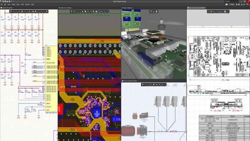
Integrating schematics, layout, simulation, and analysis in a single environment improves PCB-based product development.
Hands-On Implementation Steps
Transitioning from a static review process to a collaborative workflow takes upfront planning. Engineering managers can implement this transition through four practical steps:
- Establish a central component library in the cloud to boost the reuse of preferred components. Enforcing a library structure guarantees that all designers pull from the same pool of verified, high-quality assets.
- Connect your component library to real-time distributor databases to help engineers make well-informed choices about parts and pricing from the start, preventing late-stage surprises.
- Replace repetitive manual tasks with automated systems for part requests, reviews, and version publishing to standardize processes for greater consistency and speed.
- Assign clear permissions for who can view, edit, and approve design data and use SSO for easy, secure access management across your team.
By abandoning static PDFs and disjointed communication, your organization can directly address the obsolescence of traditional review practices, shifting design review from an administrative impediment to an active, multidisciplinary process. This change enables you to catch mistakes early, secure supply chains, and accelerate hardware delivery. Start making these changes now to modernize your review process and allow your teams to deliver higher-quality products faster than the competition.
All images used courtesy of Altium.
Related Content