Facebook
 Google
 GitHub
 Linkedin
Electronic Components Resistors
Video Lectures created by Tim Feiegenbaum at North Seattle Community College.
Resistors
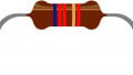
Continuing in Section 3.3, we're looking at the component resistors. Resistors are fundamental components in electronic circuits. A resistor is constructed to have a specific amount of resistance to current flow. The range of resistors may be from less than one ohm to well over 20 million ohms or 20 mega ohms. Fixed resistors have a single value of resistance but variable resistors can provide different values of resistance. Here have a few resistors over here in this nice little image.
Here's a photograph of a whole bunch of resistors. Resistors are rated by their value of resistance and the power they can safely dissipate. Every resistor has a power rating. The power rating is to a large degree determined by its size. The greater the surface area the more power it can dissipate. Power ratings of resistors vary from less than from one-tenth of a watt to many hundredths of watts.
Resistor tolerance is a measure of the resistor's variation from the specified value. Resistor tolerance is expressed as a percentage of its nominal value. Typical resistor tolerances are one percent and five percent, with tighter-tolerance resistors being somewhat more expensive. If you have a need for high-tolerance resistors typically, you will pay for them. They are referred to as precision resistors. If the resistors have tolerances of less than two percent, typically they are referred to as precision resistors.
Resistor Technology
There are four major classes of fixed resistor technology. We're going to be looking at, let's see the first one is carbon-composition, then we're look at film resistors, we'll look at wire wound and we'll also look at surface-mount technology. Now let's get back to our first one here.
The first one is carbon-composition. They are made of finely ground carbon. This is a loss of low resistive material. Then they're also made with powdered filler. This is a high resistance material. The ratio of carbon to filler material determines the resistance. This is the idea, carbon-composition they're made of carbon and this powdered filler. The ratio of the carbon to the filler will determine the resistance. Power ratings can be increased by making the resistor larger.
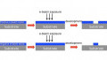
Film resistors, they're made by depositing a thin layer off resistive material onto an insulating tube or rod called the substrate. Here we have the substrate in here. This is commonly ceramic or something of that nature. It's made by depositing a thin layer of resistive material around that substrate. The leads are attached to the end caps, which contact the resistive film. Here we have the end cap. There would be one on this side as well and they're attached to the leads. The resistive layer is trimmed with an industrial laser until it has the desired resistance. You're going to have that coating of resistive layer and then the industrial laser will trim it off until you have the resistance that you desire.
I have a little line here that says, "Less is more." The idea here is that the thinner the layer of resistive material, the higher the resistance will be. This method is called spiraling and produces resistors very close to the desired valves. This is referring to the use of the industrial laser to trim them. Here again is a cutaway of a film resistor. Here is the substrate, often times it's the ceramic and then the middle, metallic film is what is the resistive material. Then this is the coating that would cover the resistor.
Then we have wire wound resistors. They are made by winding resistors wire around an insulating wire. Here you see the windings around this resistor. The ends of the wire are connected to leads and the body of the resistor is coated with a hard-insulated jacket. Here we have the as the leads and then here's the coating. In this case, the resistor value is determined by first of all the type of wire and then the diameter. How thick is the wire, the thicker the wire the less the resistance and the length of the wire, the longer the wire the great the resistance. They're used for high power and precise values. Let's see here we have a term it says, "Alloy resistance wire wound to specific perimeters including TCRs. Now TCR means Temperature Coefficient of Resistance from + or - 20 to 5500. The ppm is parts per million per centigrade for parts for million per degree, parts per million per degree centigrade.
Then we have Surface-mount technology. These have no leads. Their contacts solder directly to the circuit board pads. Pictures to the right here we have a surface-mount. Then here is example of the leads here. This piece here would actually solder to the circuit board. This is a cutaway of a surface-mount resistor, a photo of several surface-mount resistors compared to the head of a pen are showed down here. Here you see the surface-mount components, here's the head of the pen. You see that these are quite small.
Surface-mount resistors are used on computer system boards and other applications where components need to be very small. Surface-mount resistor markings, many surface-mount components have no visible markings and must be measured with test equipment to determine their value. Some manufacturers indicate the value of a surface-mount resistor with a numerical code. The first digit or digits indicate the value of the resistor and the last digit the multiplier. If you had the number 103, it would mean 10 with three zeros and this would be indicating 10,000 ohms. This case over here, here was the first one here. You have a 39 with a one so this would indicate 390 ohms. In this picture above, this is a circuit board. You'll notice right here you see that component, this one, this one and this one. Those are all surface-mount resistors.
Resistor Color Code (3 - 4 Band)
Resistor color code, we're first of all we're going to look at three and four band resistors. Since resistors are physically small, it's impractical to print the value of the resistor on it. Manufacturers mark resistors with three to five colored bands that indicate their value. Three or four band resistors can be interpreted by the following procedure.
Now we're going to talk about five-band in a few moments, but for right now we're looking at three and four band. This one happens to be a four-band component. The first two bands represent the first two digits of the resistive value. We haven't talked about color code yet. In this case the yellow and the purple would indicate the resistive value. Then multiply the digits obtained in step one by the multiplier value. In this case, the orange here's going to indicate how many zeros this will be. The first two we're going to indicate a numeric value and then we're going to add a number zero specified by the third.
If a fourth band is present, it indicates the tolerance. If there's no fourth band the tolerance is expected to be + or – 20 percent. In this particular case when we talk about three or four band, the idea is the four-band then there's going to be a band here that indicates the tolerance. If it's simply a three-band resistor, the tolerance is expected to be 20%.
Now resistor color code, this is something if you work in the electronics industry you're going to have to memorize this code somehow and there is all kinds of little, new monarchs out there to memorize it. I'm not going to go into them some of them are unsuitable for putting on our recording. Anyway so here we have black, brown, red, orange, yellow, green, blue, violet, grey and white. These various colors will translate to the stripes that we have on the component.
Just to look at these components in parallel with what we've got here, yellow, the first stripe will be four, and then this is violet, violet is seven and then that will give us 47. The third stripe here, which is orange, will mean 47K, 47,000, and then the silver here would indicate that it is 10 percent tolerance but this is how you would use this color code information. This is one of those things like I mentioned if you are going to work in an electronics industry, you're going to have to literally memorize this information.
Here we have the four codes we just talked about this one here. This is another example. If the first stripe is red, that would indicate a two, and here we have violet which is seven and orange which is three and that would indicate three zeros. This is 27,000 ohms, we would usually write that as 27K ?, like that. The silver indicates that this has a tolerance of 10 percent. This is the technical data about this component.
Then here I brought this resistor back, the resistor below has the four color code, again this is a four color code. This is the actual component and again we had 47 this is the 4, 7, the orange indicates the three zeros and so that is 47K and we already talked about the silver that means 10 percent tolerance. Now, I actually connected this up to my handy dandy little digital ohm meter and this is the component connected across the negative and the positive terminals of the probe leads. You can see the measurement here, one of the reasons I did this is because it doesn't say exactly 47K, it says 47,100. That lens credence as to why I'm mentioning this here, given 10 percent tolerance as measured value would be, it could vary between 42.3K to 51.7K, so that means 10 percent tolerance, it means it's 47K and that would be plus or minus 4,700 ohms.
Now you'll see that this is well within the tolerance but the silver stripe says it will be within 10 percent. Now it doesn't mean it will be 10 percent off but it means it won't go outside of that tolerance.
Precision Resistors
Then we have precision resistors and these typically they have five bands instead of four. Now it's very similar to what we just looked at with the three and four band components which is the little bit of variation. With these, the first three colors indicate the resistance value. Remember with the four-band the first two now we are going to use the first three. The fourth band is the multiplier which is the same as we did with four-band. The fifth band is the tolerance.
Now again another thing is with the fifth, with precision resistance we have, a different set of colors here more colors, let's put it that way. We have some much tighter tolerances that these components will comply with. I think I have a picture on the next screen, okay here is a five color and so this particular component, the first band is red for two, violet for seven, Brown for one and then orange again is three so that will be three zeros so this would be 271K?. Since the final stripe is, green we would see from over here that green is 0.5 percent so this would be within half a percent of this value. That is a precision resistor using the five bands striping method.
Let's see, there is another standard which uses the fifth band as a reliability index, now the first four would be, well obviously the first, excuse me. The first two are going to indicate the first two digits then you have the multiplier and then you have the tolerance band. But the fifth band is a reliability i.e. a failure rate and you will note here, if its brown it means it has, these components will typically, one percent of them will fail after a thousand hours of use.
Then as the reliability factor goes up if it was yellow, only 0.001, one thousandth of one percent of this will fail after a thousand hours of usage so those will be very high precision resistors with extremely high-reliability rate.
Variable Resistors
Variable resistors, sometimes it is desirable to change the value of a resistor installed in a circuit. The resistance of a variable resistance is controlled by turning it could be a knob, could be rotating a screw, or could be moving a slider. Anyway, you can vary a resistor if it is in fact a variable resistor. Now there are two major classes of variable resistors so its rheostats and potentiometers.
Rheostats they usually have two terminals and the resistance between the two terminals changes. Potentiometers they usually have three terminals and the resistance between the two end terminals does not change. Let's take a closer look at these. There are some examples of variable resistors and here is one where they change it by turning a screw and this one you change by turning the screw again. Most of these are by turning a little screw. These actually have a big knob and you would actually, this looks like, this has a knob, you physically turn this one as the one you would adjust with a screw. They come in all different sizes and shapes.
Rheostats
Now we are going to look at what is a rheostat and then compare it to a potentiometer. Now important thing to remember about a rheostat is that a rheostat has two connection points and so here, we have a rheostat, I'm going to show this is one connection point and this is another. Maybe I'll put a ground down here. The, maybe I'll put a circuit here, let's see if I put a circuit in here, maybe I'll put a, let's pretend this is a light bulb and it will come up here and will connect this to 15 volts.
Here we have this situation the arrow indicates an adjustment. Okay so here we had this arrow and that means that this can be adjusted. If the arrow rises, the resistance across the two points increases. You will see that the path for current comes up here and it's got to go to the end. If the arrow was down at a low point that current can just pass right through here in fact, if this was adjusted way down to a point maybe down here, then there would be zero resistance.
Likewise if this arrow was across up here then current would come up and it would have to go through virtually the whole component. Now why would you do this? Well in this particular session that ways in the way I have drawn this, remember that current equals voltage divided by resistance and in this particular case, we are varying resistance through the circuit.
As the resistance goes down the current goes up and if we have this light bulb here, that light bulb will get brighter. This could be a circuit to dim or brighten this light switch. Anyway, the important thing we are trying to get out here is a rheostat and a rheostat has two connections and it is used as a variable resistor.
Potentiometers
Then we have a potentiometer. Now potentiometer has three connection points. Now notice here we have ... Let's just pretend this is ground here. We have this connection point we have a connection point here and we have a connection point here. If we were to go up here and connect this to say, we connected this again to 15 volts. Now in this particular case, you'll notice that the resistance between here and here remains unchanged. That repeating a value over here, that's based on how much resistance is being picked off when this arm is adjusted.
If we were to go over here, we could use this as a variable control for voltage. It could go from zero to 15 volts. This is a potentiometer.
Resistor Symbols
Then we have the symbols for these resistors. Here's a symbol for a rheostat, notice the arrow indicating that it is variable and note that there's connection points. This is the schematic symbol for a potentiometer. Notice again we still have the arrow indicating the ability to vary. Notice that there are three connection points. The resistance between here and here does not change but the value that's read off of here will vary based on where this adjuster is placed across that component.
Now here is a potentiometer connected as a rheostat. If you look at this circuit, you'll see it looks very similar to this except that the end has been tied around and connected to the top. Now this is a potentiometer that is connected the function as a rheostat. Notice at [inaudible 00:21:59] we two connection points, which makes this a rheostat by its potentiometer, which has three. Then this is another potential connection using a potentiometer for a rheostat. In this case, the bottom of the potentiometer is not connected so we're just using this connection point and this connection point. Again, we have two connection points, which makes it a rheostat.
Okay, this brings our lesson on resistors to a conclusion. We've looked at rheostats; we've looked at potentiometers. We talked a little bit, well here variable resistors; they come under the categories of rheostats and potentiometers. We looked at precision resistors using five band color codes. We looked at resistors using the three and four band color codes. Here we have our color, it's imperative that you memorize this color code if you're going to work in the field of electronics.
We talked about surface-mount. We talked about four types of resistors, the surface-mount, wire wound, film, and carbon-composition. That concludes our session on resistors.