 Facebook
 Google
 GitHub
 Linkedin
Wire and Cable
Video Lectures created by Tim Feiegenbaum at North Seattle Community College.
Wire and cable are generally used to interconnect various components in electronic systems. Wire is a good conductor, but it is not perfect because it has some resistance. Incorrect wire selection can degrade system performance and in some cases present fire hazards. It's imperative that the right type of wiring be used for the given application. The amount of resistance a wire offers to current flow depends upon, and there is a table in your text, 3-3, that addresses this particular subject. We're going to be looking at four items that will impact resistance to current flow. We will look at type of material, temperature, length and cross-sectional area.
First of all, let's look at type of material. Common wiring materials are copper, silver, gold, sometimes aluminum is used and there's a wide variety of metals that are used for wiring. Different materials will have different resistances. If you look in this table you'll note that based on the type of material, the resistance will vary. Now within the same materials, the resistance will be different based on the diameter of the wire. A thick wire will have a lower resistance than thin wire made of the same material.
Temperature: The temperature coefficient of wire is typically found in reference books. As a rule, resistance is directly proportional to rising temperatures. If you look on Table 3-3 they show the resistances at 20 degrees centigrade and at 70 degrees centigrade. You will see that they're not the same. Most of the time, the warmer the wire the higher the resistance. Now, the resistance of some materials, like silicon and carbon will go down with higher temperatures. These are not typically used for wiring, but just keep in mind that this is not a universal rule that as heat goes up that resistances go up. There are a few materials where that rule will not apply.
The amount of resistance a wire offers to current flow depends upon, and then there are two more items here. The length: Data sheets often give resistance per 100 ft. Your text provides for 100 and 1000. This has to do with the resistance. For example, if you had 100 ft of wire and let's say that it had 5 ohms of resistance in 100 ft, if you extend that out to a 1000 it's going to be 50, so it's a directly proportional relationship.
Then cross-sectional area and this is expressed in circular mils. We have a formula here. We're going to talk about that a little more in the next page. I'll just mention, this is not really the correct formula but it is close and your text chooses to use it for simplicity. The larger the cross-sectional area, the lower the resistance will be. If you have two cables, let's pretend these are two cables here. This one has a larger cross-sectional area than this one, so this wire with the larger cross-sectional area will offer a reduced amount of resistance than the same material only at a smaller circular cross-sectional area.
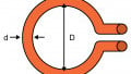
Cross-Sectional Area of Wire
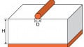
Let's see. The unit of measure for the cross-sectional area of wire, it's called circular mils. The formula below is based on the diameter of the wire. Keep in mind, a mil represents 1/1000ths of an inch. The area of circular mils is defined by D squared, and so D squared is going to be--this is the diameter here and squaring that will give us the circular mils. That is actually the square area of this entire--and that's not exactly accurate, because these areas here are included. The actual formula is this. As I mentioned earlier text, [inaudible 0:04:57] information on this formula just for simplicity, so we will use this formula in this course.
Wire Sizes
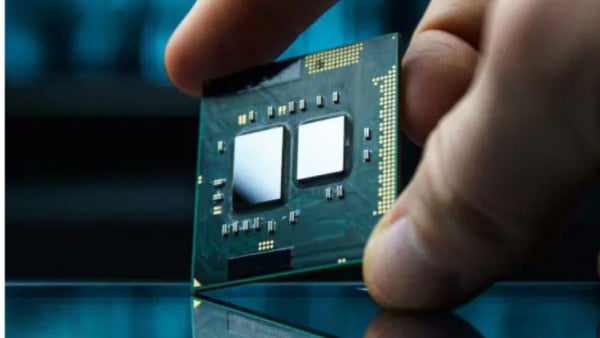
The current that must pass through a wire generally determines the size of the wire used. The current that must pass through a wire generally determines the size of the wire used. Some are microscopic like the wires that connect microprocessors. You have others, you have power transport wires. Often these are an inch in diameter. They're huge. The current-carrying capacity of a wire is referred to, and here is the term, ampacity. Wire that is too small for the current will drop excessive voltage because of the resistance of the wire, in many cases causing the wire to dissipate power. If you have a wire that is too small and you're sending too much current through it, the wire will drop more power in the form of watts because of the higher resistance of the wire. This can cause the wire to overheat. This potentially can cause fire.
Wire is specified by gauge numbers. There are at least six different industry standards for assigning a particular wire size to a particular gauge number, not all of which are the same. The most commonly used system is the American Wire Gauge (AWG). We have a table 3-4 in your text that shows the American Wire Gauge table. It specifies the following things. It assigns an American Wire Gauge Number and this starts out at 0000 and it goes up to 30. It specifies the diameter of the wire. It specifies cross-sectional area in circular mils. It also specifies the ohms per 1000 ft of Annealed Copper wire at, and notice a specified temperature, 20 degrees centigrade. The annealing process has to do with treating the wire during manufacturing to maximize conductivity.
Types of Wire and Cable
There are many types of wire to choose from for a given application. There's a solid type and then there are the stranded type. A given wire gauge of stranded wire consists of smaller wires braided together, such as this. The final gauge size of the wire is determined by the overall diameter of the wire. For example, right here. Stranded wires are less prone to breakage when flexed repeatedly. If you have an application where the wire is going to be bent significantly or periodically or regularly, you should use the stranded type. If you have an application like an electrical wiring systems in households, you'll probably use the solid type because once it's inside the wall it's not be given lots of bending. That would probably be the choice in that particular case.
Types of Insulation
Most wires used in electronics are covered with some form of insulation. In your textbook, table 3-6 provides information about insulation. Insulation prevents shorts to other wires and the probability of shocks. The purpose of insulation is to prevent the shorting to other wires and to prevent the user from getting shocked when touches the outside surface of the wire. Many different materials are used in insulation. They vary in ways that include the following. Some of these are mentioned in table 3-6.
First one here is material. There are many different types of materials used in insulation. They include Kynar, Neoprene, PVC, Silicon, rubber, Teflon, etc. The different insulation's also will have an associated breakdown voltage. This is a potential difference that will cause the insulation to break down. Obviously, if you're putting in some kind of wire for some purpose, you want to make sure that you are not going to have a voltage that will exceed the breakdown voltage. Because if it does, the insulation will lose its ability to stop current flow so current will flow through the insulation and the insulator will be permanently damaged. Other items that are considered in insulation are usable temperature ranges, resistance to water and chemicals, cost and mechanical flexibility.
Single-Conductor Versus Cable
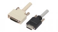
Individual insulated wires may be bundled in a common jacket. The bundled assembly is called a cable. Down in the lower picture you see a cable that has individual wires inside it. We typically call this a cable. This picture up here is kind of pretty, I think these are actually supposed to be fiber optics but it is a cable. It contains these--I'm calling them wires, though I think the intention is to call them fiber. You get the idea. The idea of cable is that you have individual wires within a bundle. The number of conductors in a cable varies from two to over a hundred. Many Ethernet systems commonly include large numbers of twisted pair wires within one large cable. Individually the wires could be solid or they may be stranded.
Coaxial Cable
Coaxial cable consists of an insulated center conductor surrounded by a braided wire shield. Here we have the center conductor and this is the braided shield. A tough outer jacket encases both the center conductor and the braided shield. This is the outer conductor or the outer jacket right here. The braided shield is typically connected to a zero-volt potential in most applications. This provides a barrier preventing stray fields from inducing noise voltages into the center conductor. It's not addressed in your book but there are a couple of things that address that influence. One of them is Ingress and this is unwanted signals getting into the cable. Hopefully the braided shield will prevent that. Also, there is Egress and that is the phenomenon of signals that are supposed to stay inside the cable get out of the cable. The FCC actually monitors Egress. Coax comes in many sizes and shapes to accommodate and there's just a whole bunch of different uses for cable and trunk lines, feeder lines, aerial lines, buried cable, and just many other applications. There is a course here at North Seattle called EET 135 and it directly addresses the cable industry. In that course we look at the many different types of cable and the many different types of applications for cable.
Ribbon Cable
Ribbon cables are multiconductor cables in which insulated wires are formed side by side. Here we have a piece of canvas and the cable used inside a computer. Ribbon cable is frequently used to interconnect circuit boards, hard drives, floppy drives and devices in computer systems, such as this piece right here. Some types have a braided shield that surrounds the entire cable. This one doesn't but there are some that do. If necessary, individual wires can be split out and soldered. If you needed to you could... In fact, sometimes in floppy drive cables they actually cut one of the cables and that is the way they designate cables as cable select. They do that by actually cutting one of the specific ribbon wires. If necessary, individual wires can be split out and soldered individually. Typically crimp-on connectors are applied to the cable ends.
Troubleshooting Wire and Cable
Defects in wire and cable can generally be found using, notice, an ohmmeter, as long as power is removed from the system. Common defects that can be identified with an ohmmeter include: One or more open wires, two or more wires shorted together, or one or more intermittent connections. One or more wires open, okay, if you have a given wire you can use your ohmmeter and connect one end. Connect the end and you should read zero ohms on your ohmmeter. If you're reading infinite ohms then it means that there is an open in this particular wire. An old electrician's trick, sometimes if you have a wall outlet and let's pretend for whatever reason voltage is not getting to this outlet, there will be a circuit breaker that's associated with this. Usually what a technician would do is they go to the circuit breaker and they would measure the voltage at the circuit breaker to ensure that voltage is in fact there because maybe the circuit breaker has popped. These wires will go to this particular circuit.
Notice it says here, “as long as power is removed from the system,” and the electrical trick that electricians do is that if they suspect that one of these wires is open, they would remove these two wires. First they'd turn the power off and they'd remove these two wires and they would short these together. Then they would come over here with their ohmmeter and they could measure this point and measure this point. They should read zero ohms because they're measuring from here through the circuit, back over to them. They should see zero ohms. Now if they read infinite ohms it means that there is a break in this wire and that something has to be done about it. That's just one way; just one application of using an ohmmeter to diagnose an open wire. By the way, this is not a course addressing how to be an electrician. There are other courses that do that. This is just simply an example where you would find an open wire where is not obvious. In this case it would be inside a wall.
Then you have a situation where two or more wires are shorted together. If in fact that was the case, if these two wires were shorted together... Let's just draw out another application here. If these two wires are shorted together then if the ohmmeter is inserted into the circuit you measure from here to here, and there's a short here, you're going to see a dead short where there probably should be an open.
One of the more difficult problems here, we have one or more intermittent connections. Intermittent connections are always difficult to troubleshoot because they come and go. You can't really trouble shoot it unless it's failing. The problem with them is that you go in to troubleshoot and suddenly it's working. Now the measurements are normal and you have to wait until it fails until you actually get a reading that tells you something is wrong.
Okay, this has been an introduction to wire. We ended up looking at troubleshooting wire and cable. We looked at ribbon cable, coax, single-conductor versus cable. We looked at insulation. We talked a little bit about stranded versus single-conductor. We looked at wire sizes, ampacity. We looked at cmils; circular mils. We looked at the things that affect resistance, being the type of material, temperature, length, cross-sectional area. That concludes 3.2 Wire and Cable.


Very good thank you