 Facebook
 Google
 GitHub
 Linkedin
Estimating Wireless Range
How to estimate wireless communication range from radio parameters.
How to estimate wireless communication range from radio parameters.
Recommended Level
Beginner
Motivation
When designing a system with a wireless component, an important thing to know is how far two devices can communicate. Prior to doing any real design, quick calculations are needed to predict the behavior of the system. Typically, a radio system will either not tell you the range, or it will give you a vague idea. This is usually deliberate! It is very difficult to determine the radio range when the environment is not known. Even if the environment is known, there is no perfect model available to determine range, and in many cases empirical measurements are the only way to measure. Then why, you might ask, are we even bothering with any equations? The answer is that while the equations are not perfect in all scenarios, they give a good approximation and are a great starting point for the design. With this information, you can decide where to devote design time or more money to improve the range.
Friis Transmission Equation
Harald T. Friis developed what is now known as the Friis transmission equation in 1945 while working at Bell Labs. This equation combines several radio parameters in order to estimate the link budget. The link budget of a system is a way to add up all of the elements of the system. Typically expressed in decibels to make calculations easier, the link budget adds up all of the gains (adding to the range) and the losses (subtracting from the range). Here is the Friis equation:
$$P_r=P_tG_tG_r(\frac{ \lambda }{ 4 \pi R})^2$$
| Pr | Received power |
| Pt | Transmitted power into the antenna |
| Gt | Antenna gain of the transmitter |
| Gr | Antenna gain of the receiver |
| λ | Wavelength of the signal |
| R | Distance between the transmit and receive antennas |
Link Budget
A link budget is very similar to the equation above. The difference is it adds additional loss terms. These loss terms could be margin, multipath, fading, atmospheric interference and many others. Each of these losses are compex and could have their own article. For the purposes of this article, I've lumped them all into one variable, Lm, called link margin. The link margin is a good way to estimate range in non-line-of-sight environments, such as offices. A good rule of thumb is to use ~10-20dB of margin depending on the environment and reliability requirements of the connection. In very clear line of sight applications, the link marging can tend towards zero.
$$P_{RX} = P_{TX}+G_{TX}-L_{FS}-L_M+G_{RX}$$
where LFS is the path loss converted to units of MHz and miles:
$$L_{FS}=(\frac{ \lambda }{ 4 \pi R})^2=36.6dB+ 20log(f_{MHZ})+ 20log(range_{miles})$$
Example
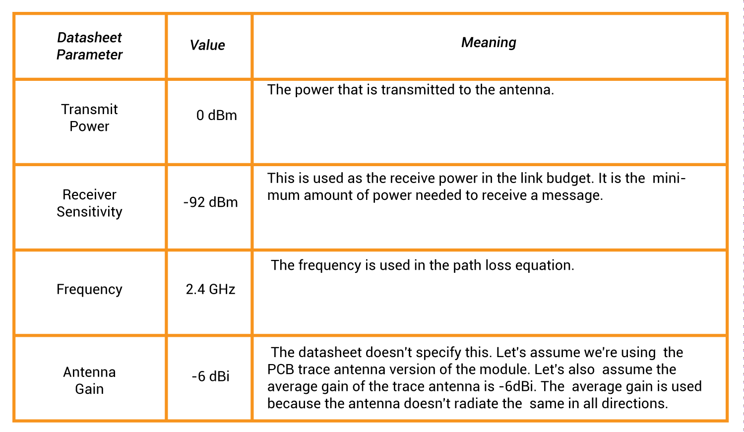
Let's analyze the popular radio module XBee® 802.15.4 (Series 1). Here are some key specs from the datasheet. According to the datasheet, this module gets 100ft inside and 300ft outside.
Solving the link budget equation for range and f=2400MHz:
$$range= antilog(\frac{P_{TX}+G_{TX}-L_M+G_{RX}-P_{RX}-104}{20})\text{ miles}$$
Outdoor
Plugging the values from the datasheet into the equation and setting the link margin to zero.
$$range= antilog(\frac{0dBm-6dBi-0dB-6dBi+92dBm-104}{20})\text{ miles}$$
$$range = 0.0631 \text{ miles}$$
$$range = 101.54 \text{ meters}$$
$$range = 333.15 \text{ feet}$$
This is the same value the datasheet shows, so our estimation of the antenna gain is probably reasonable.
Indoor
For indoor, the link margin is changed to 10dB to account for the multipath that is typical at 2.4GHz.
$$range= antilog(\frac{0dBm-6dBi-10dB-6dBi+92dBm-104}{20})\text{ miles}$$
$$range = 0.02 \text{ miles}$$
$$range = 32.11 \text{ meters}$$
$$range = 105.35 \text{ feet}$$
External Antennas
Let's say we want more range and have the capability to use larger antennas, such as a Yagi. We could use the external antenna module with the Yagi, which could change our antenna gain to 10dB if we pointed the Yagi's at each other. Since we'll get much larger distances, it's better to keep the link margin at 10dB even though we'll be outdoors. This will account for items that may get in the way, such as trees.
$$range= antilog(\frac{0dBm+10dBi-10dB+10dBi+92dBm-104}{20})\text{ miles}$$
$$range = 0.794 \text{ miles}$$
$$range = 1278.35 \text{ meters}$$
$$range = 4194.05 \text{ feet}$$
That is a big range! The downside to this arrangement is that the Yagi antenna must be pointed in one direction. The range if the Yagi was pointed in the wrong direction would be very poor.
Potential Improvements
Antenna
Just like in the example, if a bigger antenna is used, the gain will typically improve. This can be a problem in small embedded devices because it is undesirable or impractical to have the antenna sticking out of the device. Ideally when designing something, the largest antenna possible is used.
Transmit Power
The transmit power in typical embedded devices is bounded by regulatory agencies such as the FCC, cost, and power consumption. The FCC 15.247 limits 2.4GHz devices that use spread-spectrum modulation techniques to 30dBm and particular bandwidth requirements. Typically the limit for devices is not the power, but the bandwidth. Complex filters are needed to limit the bandwidth, which effectively limits the transmit power to 20dBm. In the example, if we added a power amplifier to the device, we could add 20dB of gain to the system, which would greatly improve range. The trade-off is that the amplifier adds cost and power consumption to the system. The additional power consumption can be a problem for battery powered devices.
Receive Sensitivity
Receive sensitivity is dependent on the noise figure and required signal-to-noise ratio of the system. The noise figure defines how much noise the circuitry is adding to the received signal. The lower this number is, the better the receive sensitivity is, because less noise is added. The signal-to-noise ratio required to receive is dependent on the modulation technique used. Typically, the higher the data rate of the system, the more bandwidth is needed. This means the receiver must capture more signal, which means more noise is captured.
Conclusion
Range is an important metric for any wireless system. The range is dependent on many variables. In general, more power, slow data rates, and larger antennas will allow for longer range and more reliable communication.


that range is calculated for two zigbee modules comunicating each other?
shall I have a pdf file for this one,please.
Where does the 104 come from?