Facebook
 Google
 GitHub
 Linkedin
Electronic Components
Video Lectures created by Tim Feiegenbaum at North Seattle Community College.
In this final section introducing components, we will look briefly at capacitors, inductors, transformers, switches, transistors, diodes and integrated circuits. We will look at these components in greater depth in later chapters.
Capacitors
To the right here is a schematic symbol for a capacitor. A capacitor is a basic electronic component that stores electrical energy in the form of an electrostatic field. The operation of nearly every electronic system depends upon capacitors. They vary widely in their size and appearance. In your textbook, there are several pictures of capacitors that you commonly see and I have put a couple of examples of capacitors here that bring out the idea that they vary widely in size and appearance. This capacitor to the right this is very large and it is actually a 20,000-volt capacitor meaning that it could once it's charged up, it could hold a charge of 20,000 volts.
Now, to the left is a piece of computer memory and this is a DRAM module that is for Dynamic Random Access Memory. DRAM modules are actually built with microscopic capacitors. Now, this particular module is a 256MB module. Now, a byte holds eight bits of information and each of those bits are going to be one of these microscopic capacitors. If this is holding 256 million bytes and that's going to be times eight, we would have roughly in the ball-park of two billion capacitors on this little piece of RAM. Anyway, this is a comparison that they can be very small and they can be very large as well. We will formerly address capacitors in Chapter seven of your text; we're just introducing them at this point.
Inductors
Here is the schematic symbol for an inductor. An inductor is also a fundamental electronic component sometimes referred to as a coil. It consists of a spiraled or coiled wire. The inductor stores electrical energy in the form of an electromagnetic field and here we have some pictures of inductors.
Transformers
Again, here is another schematic symbol down here for a transformer. A transformer is basically two or more coils whose electromagnetic fields interact. Here's one coil, and here is the other coil; transformers are used to increase or decrease alternating voltages. Uses include stepping down voltages for use in computers and many other electronic devices. Now as an example, a personal computer you plug it into the wall 120 volts, 60 cycles does the computer need that high a voltage? Well, the answer is no and so the transformer is used to step that voltage down to a much lower level actually the computer is going to operate the highest voltage it needs is only 12 volts DC. The transformer will step it down and then will use some diodes to create a device called a rectifier, which will step that voltage down and make it into a DC level.
They're also used for stepping up voltages for high voltage applications. There are some applications where in the case of if we're talking about 120 volts where we would want that 120 volts to actually be a higher level and the transformer could also step that up. We will look at transformers in more depth, as well in later chapters.
Switches
Switches are yet another group of basic electrical devices. Switches break or make circuit connections and often the term is used, they open or they close connections. Here we have a picture here we see a battery, a light bulb and here is our simple switch. Here the switch is opened and here the switch is closed, so here the connection is broken and here the connection is made or closed.
Then we have a number of different types of switches and this is by no means all switches but this is representative of some of the switches that are used in electronic systems. Here we have this first one we'll look at is a single pole single throw. Now we have this term single pole single throw what does that mean? Well, the pole in a switch is the movable part so here you see this is the part would move and in fact, in all these switches you can see there's actually a part that will move.
The term throw refers to how many circuits are opened or closed during the switching operation. In this case, there is one circuit here and it is either energized or it is de-energized hence the term single throw. Now in this particular one what we have here each of these dots indicates a different circuit. In this case, this particular pole could activate one of two circuits, so it's a single pole one movement but double throw in that it can throw two different circuits. Here is a double-pole single-throw. Now here is an interesting one here is a double-pole double-throw.
Over here, we have some push button circuits, this one is normally open, this one is normally closed, this one could be maybe a doorbell or something like that. You push the push button and momentarily it does something. This one is on constantly you push the button to turn it off momentarily.
Then here we have a three-pole four-position switch. Here we see three different poles and in each pole, there are four possible positions. Now like the position to this particular switch is in disconnection is made here and there is a connection here so currently, we have a connection between here and here. As its rotary switches turn, we could pick off these connections, this one or this one and so hence, we have four possible positions here.
This is the schematic of a relay. Now this is what you would see in Electronics Workbench. You see this Key=A when you begin using your simulations software, what this would mean is Key=A means that if you press the letter A on your keyboard it would cause this switch to activate.
Single Pole Double Throw
Now here we have an actual circuit using a single pole double throw switch. In this circuit S1, okay S1 is a single pole double throw switch meaning, so one possible piece moves or one movement piece, which is the pole and double throw which means that there are two possible circuits that can be activated. The idea here is that in this particular position, this circuit is activated and this light is operating. If the switch is activated and we switch it to the other position then this is activated so hence the term double throw.
Now again this Key=A here again this comes from Electronics Workbench simulation software so what all these would mean is if you were using this in Electronics Workbench if you press the spacebar it would change the position of the switch.
Basic Switch Operation
This is just a review of what we've just looked at. The pole is the switch the pole in the switch is the movable part. The term throw refers to how many circuits are opened or closed during the switching operation. A double throw switch opens or closes two circuits on each pole. Basic switch types include and this is single pole single throw, single pole double throw, double pole single throw, double pole double throw etc. Some switches do not maintain contact when operated and are called momentarily contact switches and these include doorbells, horns, keys on a computer keyboard are examples.
Relays
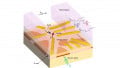
Relays are switches, okay the difference is that relays are electromagnetically operated switches. They're used extensively in electrical systems, especially industrial systems. Relays are used for motor control circuits, circuits to protect workers, switching circuits and power switching. We have a graphic image of a relay. Let's take a look here. This relay has double pole double throw contacts. You see the contacts are over here. It represents two different switches that change state at the same time. We could have two different switches wire or different circuits connected to this circuit. They could either be simultaneously connected or simultaneously disconnected.
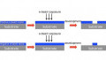
A shows the shows the state in its de-energized state. Okay this A right here, this is de-energized. 'B' is in the energized state. If you look closely, at the switch you'll see they may look the same but there's some subtle differences. You'll notice in the de-energized state you see we have actually three sets of contacts here. These two are in contact. This is in the de-energized state. Typically, a spring will be holding them in this position. Then down here, this is in the energized state. Now notice here we're applying a power supply, voltage is supplied, current is flowing through this coil. The electromagnetic field is pulling the contact pull. This piece right here has been pulled down to the lower contact. Now, this is in the energized state. It will stay energized until the voltage is removed. The spring will pull it back into the de-energized state.
These are some schematics symbols you might see for relays. I'm not going to go into these but these are just representatives of the different types of schematics you might see. The drawings do not always show the relationship between the contacts and the coil. For example, here you see the coil, you see the contacts but you don't see any … There's no ID of how are these tied together. That's commonly the way they'll be shown on schematics. Then you see the NC and the NO. The NC means "Normally Closed" and the NO means "Normally Open."
This is a Programmable Logic Controller vectors, several of them. These are the Allan Bradley design. PLCs are small computer systems used to control industrial machines and processes commonly used in automation. Relays are used in these devices as the switching elements. These will be controlling various automation functions and the switching action would be done with relays.
Transistors and Diodes
Transistors are solid-state devices or semiconductors. They are used in many electronic devices including amplifiers, computers, and industrial controls. Diodes are used to alter information signals, convert AC current into DC current and as a protective device and switch. Here's a schematic symbol for a diode, schematic symbol for a transistor and here are a number of transistors. Now, we have much more to say about transistors and diodes in later chapters.
Integrated Circuits
Then finally, we mentioned Integrated Circuits. Integrated Circuits are miniature versions of complete circuits. Many ICs have more than a million components, okay that's a million transistors, resistors, diodes, and capacitors etc. We will look at ICs in much greater depth in later chapters. This section 3.3, we have introduced many components and we will be looking at these components in greater depth in later chapters.