Facebook
 Google
 GitHub
 Linkedin
Digital Lab - Introduction
Overview
These digital circuit projects are designed to be easy to follow, relatively inexpensive to build, educational, and even fun. Each Digital Lab project includes step-by-step instructions, a parts list, schematic diagrams, and illustrations of the completed projects similar to the example of Figure 1.
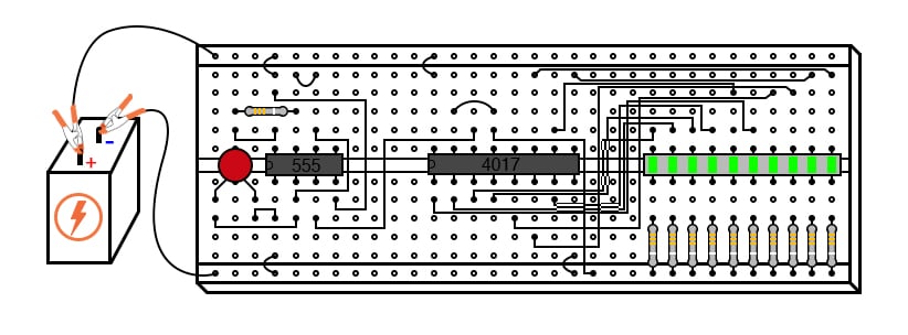
Figure 1. Example illustration of a completed digital circuit constructed on a breadboard
Digital circuits deal with signals restricted to two states representing the logic values 0 and 1. Typically, logic 0 is the extremely lower limit of the supply voltages (0 V), while the logic 1 value is represented by the upper limit of the supply voltage (VDD).
This stands in contrast to analog circuits, in which signals are free to vary continuously between the limits imposed by the power supply voltage and circuit resistances. Digital circuits find use in true/false logical operations and digital computation in countless applications, including:
- Computers
- Smartphones
- Data centers
- Automobile control systems
- Wireless communication networks, and so much more!
Digital Integrated Circuits
The circuits in the DC Lab chapter use IC, or integrated circuit, components that often called "chips". Such components are actually networks of interconnected components manufactured on a single wafer of semiconducting material. Integrated circuits providing many pre-engineered functions are available at low cost, benefitting students, hobbyists, and professional circuit designers alike. Most ICs provide the same functionality as discrete semiconductor circuits at higher levels of reliability and at a fraction of the cost.
CMOS Circuit Projects
In most of the DC Lab projects, we will primarily use complementary metal-oxide semiconductor (CMOS) technology, as this form of IC design allows for a broad range of power supply voltage while maintaining generally low power consumption levels. Though CMOS circuitry is susceptible to damage from static electricity (high voltages will puncture the insulating barriers in the MOSFET transistors), modern CMOS ICs are far more tolerant of electrostatic discharge than the CMOS ICs of the past, reducing the risk of chip failure by mishandling.
Proper handling of CMOS involves using anti-static foam for storage and transport of ICs, and measures to prevent static charge from building up on your body (using a grounding wrist strap or frequently touching a grounded object).
TTL Circuit Projects
Circuits using transistor-to-transistor logic TTL technology require a regulated power supply voltage of 5 volts and will not tolerate any substantial deviation from this voltage level. Any TTL circuits in this chapter will be adequately labeled as such, and it will be expected that you realize its unique power supply requirements.
Using Breadboards for Digital Circuits
When building digital circuits using IC chips, it is highly recommended that you use a breadboard with power supply rail connections along the length of the top and bottom, as illustrated in Figure 1.

Figure 1. Recommended breadboard power and ground rails for digital circuit projects.
These power rails are sets of holes in the breadboard that are electrically common along the entire length of the board. Connect one rail to the positive terminal of a battery and the other rail to the negative terminal. Then, DC power will be available to any area of the breadboard via connection through short jumper wires.
Some breadboards will have a pair of power rails at the top and bottom to allow you to easily route both power and ground the full length of each side. With so many of these integrated circuits having “reset,” “enable,” and “disable” terminals needing to be maintained in a “high” or “low” state, not to mention the VDD (or VCC) and ground power terminals which require connection to the power supply, having both terminals of the power supply readily available for connection at any point along the board’s length is very useful.
Most breadboards that I have seen have these power supply rail holes, but some do not. In some of the other electronics projects in this textbook volume, I’ve illustrated circuits using a breadboard lacking this feature to show how it isn’t absolutely necessary. However, digital circuits seem to require more connections to the power supply than other types of breadboard circuits, making this feature more than just a convenience.