Facebook
 Google
 GitHub
 Linkedin
Digital Lab - 3-bit Binary Counter
Project Overview
In this project, you will build the automatic binary counter with a light-emitting diode (LED) output display, illustrated in Figure 1.
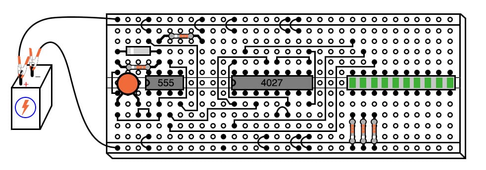
Figure 1. Digital 3-bit binary counter with LED output indicators.
A 555 timer operates as a square wave oscillator and one of the counter bits. The output from the timer drives two J-K flip-flops that complete the counter.
Parts and Materials
- 555 timer IC
- One 1N914 switching diode
- Two 10 kΩ resistors
- One 100 µF capacitor
- 4027 dual J-K flip-flop
- Ten-segment bar graph LED
- Three 470 Ω resistors
- One 6 V battery
Caution! The 4027 IC is a complementary metal-oxide semiconductor (CMOS) and, therefore, sensitive to static electricity!
Learning Objectives
- How to use the 555 timer as a square-wave oscillator
- How to make an asynchronous counter using J-K flip-flops
Instructions
It is highly recommended, in this experiment, as in all experiments, to build the circuit in stages, namely, identify portions of the circuit with specific functions and build those portions one at a time, testing each one and verifying its performance before building the next. A very common mistake of new electronics students is to build an entire circuit at once without testing sections of it during the construction process and then be faced with the possibility of several problems simultaneously when it comes time to finally apply power to it.
Step 1: First, build the 555 timer circuit, illustrated at the left side of the breadboard implementation of Figure 1 and the schematic diagram of Figure 2.
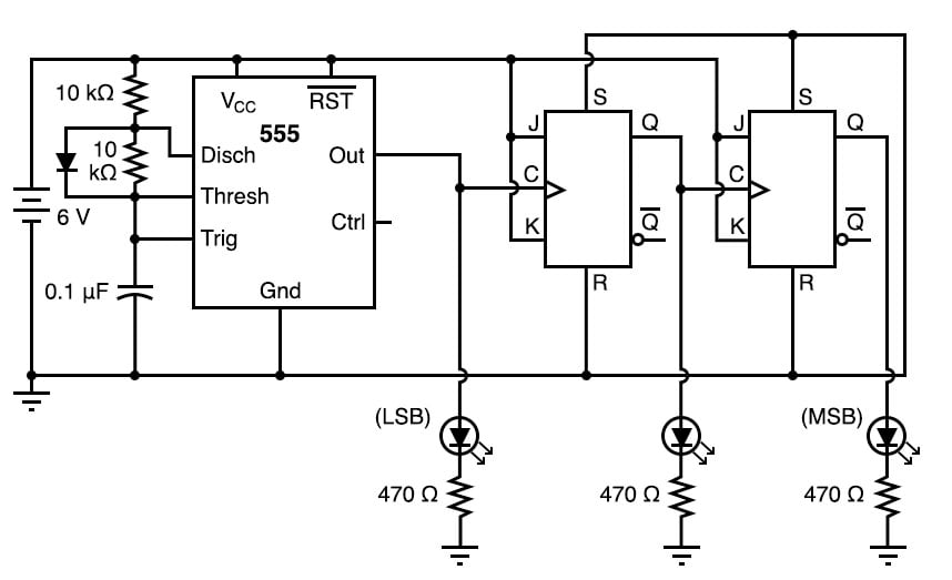
Figure 2. Schematic diagram of digital 3-bit counter with LED output indicators
Connect the 555’s output (pin #3) to the least significant bit (LSB) LED so that you have a visual indication of its status.
The 555 timer operates as a slow, square-wave oscillator with a duty cycle of approximately 50 percent. This duty cycle is made possible by using a diode to bypass the lower resistor during the capacitor’s charging cycle so that the charging time constant is only RC and not 2RC, as it would be without the diode in place.
Ensure that the output oscillates in a slow, square-wave pattern (LED is lit for about as long as it is off in a cycle) and that it is a reliable signal (no erratic behavior, no unexplained pauses). If the 555 timer is not working properly, neither will the rest of the counter circuit.
Step 2: Once the 555 timer circuit has been proven functional, proceed to plug the 4027 IC into the breadboard and complete the rest of the necessary connections between it, the 555 timer circuit, and the LED assembly.
In a sense, this circuit cheats by using only two J-K flip-flops to make a three-bit binary counter. Ordinarily, three flip-flops would be used—one for each binary bit—but in this case, we can use the clock pulse (555 timer output) as a bit of its own.
When you build this circuit, you will find that it is a down counter. That is, its count sequence goes from 111 to 110 to 101 to 100 to 011 to 010 to 001 to 000 and then back to 111. While it is possible to construct an up counter using J-K flip-flops, this would require additional components and introduce more complexity into the circuit.
Remember that a small amount of extra attention paid to detail near the beginning of a project is worth an enormous amount of troubleshooting work near the end! Students who make the mistake of not testing circuit portions before attempting to operate the entire circuit often (falsely) think that the time it would take to test those sections is not worth it and then spend days trying to figure out what the problem(s) might be with their experiment.
Related Content
Learn more about the fundamentals behind this project in the resources below.
Textbook:
Worksheets: