 Facebook
 Google
 GitHub
 Linkedin
Digital Logic With Feedback
With simple gate and combinational logic circuits, there is a definite output state for any given input state. Take the truth table of an OR gate, for instance:
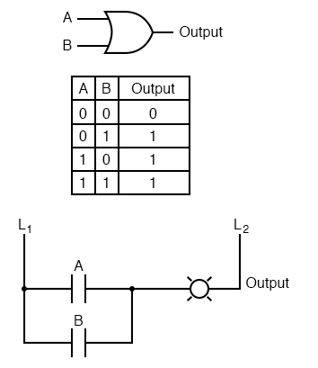
For each of the four possible combinations of input states (0-0, 0-1, 1-0, and 1-1), there is one, definite, unambiguous output state. Whether we’re dealing with a multitude of cascaded gates or a single gate, that output state is determined by the truth table(s) for the gate(s) in the circuit, and nothing else.
However, if we alter this gate circuit so as to give signal feedback from the output to one of the inputs, strange things begin to happen:
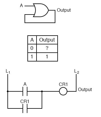
We know that if A is 1, the output must be 1, as well. Such is the nature of an OR gate: any “high” (1) input forces the output “high” (1). If A is “low” (0), however, we cannot guarantee the logic level or state of the output in our truth table.
Since the output feeds back to one of the OR gate’s inputs, and we know that any 1 input to an OR gates makes the output 1, this circuit will “latch” in the 1 output state after any time that A is 1. When A is 0, the output could be either 0 or 1, depending on the circuit’s prior state!
The proper way to complete the above truth table would be to insert the word latch in place of the question mark, showing that the output maintains its last state when A is 0.
Any digital circuit employing feedback is called a multivibrator. The example we just explored with the OR gate was a very simple example of what is called a bistable multivibrator. It is called “bistable” because it can hold stable in one of two possible output states, either 0 or 1.
There are also monostable multivibrators, which have only one stable output state (that other state being momentary), which we’ll explore later; and astable multivibrators, which have no stable state (oscillating back and forth between an output of 0 and 1).
A very simple astable multivibrator is an inverter with the output fed directly back to the input:
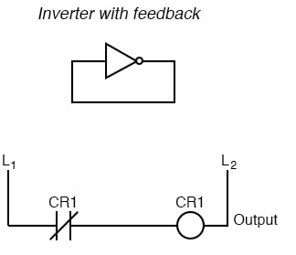
When the input is 0, the output switches to 1. That 1 output gets fed back to the input as a 1. When the input is 1, the output switches to 0. That 0 output gets fed back to the input as a 0, and the cycle repeats itself.
The result is a high frequency (several megahertz) oscillator, if implemented with a solid-state (semiconductor) inverter gate:
If implemented with relay logic, the resulting oscillator will be considerably slower, cycling at a frequency well within the audio range.
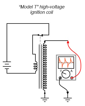
The buzzer or vibrator circuit thus formed was used extensively in early radio circuitry, as a way to convert steady, low-voltage DC power into pulsating DC power which could then be stepped up in voltage through a transformer to produce the high voltage necessary for operating the vacuum tube amplifiers.
Henry Ford’s engineers also employed the buzzer/transformer circuit to create continuous high voltage for operating the spark plugs on Model T automobile engines:
Borrowing terminology from the old mechanical buzzer (vibrator) circuits, solid-state circuit engineers referred to any circuit with two or more vibrators linked together as a multivibrator. The astable multivibrator mentioned previously, with only one “vibrator,” is more commonly implemented with multiple gates, as we’ll see later.
The most interesting and widely used multivibrators are of the bistable variety, so we’ll explore them in detail now.
RELATED WORKSHEETS:


nice, learning this right now