 Facebook
 Google
 GitHub
 Linkedin
The S-R Latch
A bistable multivibrator has two stable states, as indicated by the prefix bi in its name. Typically, one state is referred to as set and the other as reset. The simplest bistable device, therefore, is known as a set-reset, or S-R, latch. To create an S-R latch, we can wire two NOR gates in such a way that the output of one feeds back to the input of another, and vice versa, like this:
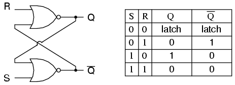
The Q and not-Q outputs are supposed to be in opposite states. I say “supposed to” because making both the S and R inputs equal to 1 results in both Q and not-Q being 0. For this reason, having both S and R equal to 1 is called an invalid or illegal state for the S-R multivibrator.
Otherwise, making S=1 and R=0 “sets” the multivibrator so that Q=1 and not-Q=0. Conversely, making R=1 and S=0 “resets” the multivibrator in the opposite state. When S and R are both equal to 0, the multivibrator’s outputs “latch” in their prior states.
Note how the same multivibrator function can be implemented in ladder logic, with the same results:
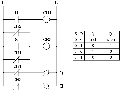
By definition, a condition of Q=1 and not-Q=0 is set. A condition of Q=0 and not-Q=1 is reset. These terms are universal in describing the output states of any multivibrator circuit. The astute observer will note that the initial power-up condition of either the gate or ladder variety of S-R latch is such that both gates (coils) start in the de-energized mode.
As such, one would expect that the circuit will start up in an invalid condition, with both Q and not-Q outputs being in the same state. Actually, this is true! However, the invalid condition is unstable with both S and R inputs inactive, and the circuit will quickly stabilize in either the set or reset condition because one gate (or relay) is bound to react a little faster than the other.
If both gates (or coils) were precisely identical, they would oscillate between high and low like an astable multivibrator upon power-up without ever reaching a point of stability! Fortunately for cases like this, such a precise match of components is a rare possibility.
It must be noted that although an astable (continually oscillating) condition would be extremely rare, there will most likely be a cycle or two of oscillation in the above circuit, and the final state of the circuit (set or reset) after power-up would be unpredictable.
The root of the problem is a race condition between the two relays CR1 and CR2.
A race condition occurs when two mutually-exclusive events are simultaneously initiated through different circuit elements by a single cause. In this case, the circuit elements are relays CR1 and CR2, and their de-energized states are mutually exclusive due to the normally-closed interlocking contacts.
If one relay coil is de-energized, its normally-closed contact will keep the other coil energized, thus maintaining the circuit in one of two states (set or reset). Interlocking prevents both relays from latching.
However, if both relay coils start in their de-energized states (such as after the whole circuit has been de-energized and is then powered up) both relays will “race” to become latched on as they receive power (the “single cause”) through the normally-closed contact of the other relay. One of those relays will inevitably reach that condition before the other, thus opening its normally-closed interlocking contact and de-energizing the other relay coil.
Which relay “wins” this race is dependent on the physical characteristics of the relays and not the circuit design, so the designer cannot ensure which state the circuit will fall into after power-up. Race conditions should be avoided in circuit design primarily for the unpredictability that will be created. One way to avoid such a condition is to insert a time-delay relay into the circuit to disable one of the competing relays for a short time, giving the other one a clear advantage.
In other words, by purposely slowing down the de-energization of one relay, we ensure that the other relay will always “win” and the race results will always be predictable.
Here is an example of how a time-delay relay might be applied to the above circuit to avoid the race condition:
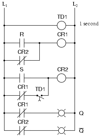
When the circuit powers up, time-delay relay contact TD1 in the fifth rung down will delay closing for 1 second. Having that contact open for 1 second prevents relay CR2 from energizing through contact CR1 in its normally-closed state after power-up.
Therefore, relay CR1 will be allowed to energize first (with a 1-second head start), thus opening the normally-closed CR1 contact in the fifth rung, preventing CR2 from being energized without the S input going active.
The end result is that the circuit powers up cleanly and predictably in the reset state with S=0 and R=0. It should be mentioned that race conditions are not restricted to relay circuits. Solid-state logic gate circuits may also suffer from the ill effects of race conditions if improperly designed.
Complex computer programs, for that matter, may also incur race problems if improperly designed. Race problems are a possibility for any sequential system, and may not be discovered until some time after initial testing of the system. They can be very difficult problems to detect and eliminate.
A practical application of an S-R latch circuit might be for starting and stopping a motor, using normally-open, momentary pushbutton switch contacts for both start (S) and stop (R) switches, then energizing a motor contactor with either a CR1 or CR2 contact (or using a contactor in place of CR1 or CR2).
Normally, a much simpler ladder logic circuit is employed, such as this:
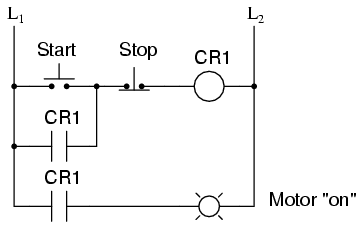
In the above motor start/stop circuit, the CR1 contact in parallel with the start switch contact is referred to as a “seal-in” contact, because it “seals” or latches control relay CR1 in the energized state after the start switch has been released.
To break the “seal,” or to “unlatch” or “reset” the circuit, the stop pushbutton is pressed, which de-energizes CR1 and restores the seal-in contact to its normally open status. Notice, however, that this circuit performs much the same function as the S-R latch.
Also, note that this circuit has no inherent instability problem (if even a remote possibility) as does the double-relay S-R latch design. In semiconductor form, S-R latches come in prepackaged units so that you don’t have to build them from individual gates. They are symbolized as such:

REVIEW:
- A bistable multivibrator is one with two stable output states.
- In a bistable multivibrator, the condition of Q=1 and not-Q=0 is defined as set. A condition of Q=0 and not-Q=1 is conversely defined as reset. If Q and not-Q happen to be forced to the same state (both 0 or both 1), that state is referred to as invalid.
- In an S-R latch, activation of the S input sets the circuit, while activation of the R input resets the circuit. If both S and R inputs are activated simultaneously, the circuit will be in an invalid condition.
- A race condition is a state in a sequential system where two mutually-exclusive events are simultaneously initiated by a single cause.


This is very helpful. Wondering, if I ran out of Nor gate ics could I directly replace with a Nand gate ic?
Sorry, a bit of actual research indicates that the two behave exactly opposite. So the answer is a definite NO.