Facebook
 Google
 GitHub
 Linkedin
Analog Lab - Introduction
Introduction to Analog Circuits
Analog circuits use signals that can vary continuously from zero to full power supply voltage. This stands in contrast to digital circuits, which almost exclusively employ all-or-nothing binary signals (1 and 0). Digital signal voltages are restricted to values of zero and full supply voltage, with no valid state in between those extreme limits.
These analog circuit projects use integrated circuit (IC) components (you might also hear these called "chips"). Such components are actually networks of interconnected components manufactured on a single wafer of semiconducting material. ICs providing many pre-engineered functions are available at very low cost, benefitting students, hobbyists, and professional circuit designers alike. Most integrated circuits provide the same functionality as discrete semiconductor circuits at higher levels of reliability and at a fraction of the cost. Usually, the discrete-component circuit construction is favored only when power dissipation levels are too high for integrated circuits to handle.
In this chapter, each project will provide step-by-step instructions, a parts list, schematic diagrams, and illustrations similar to that shown in Figure 1.
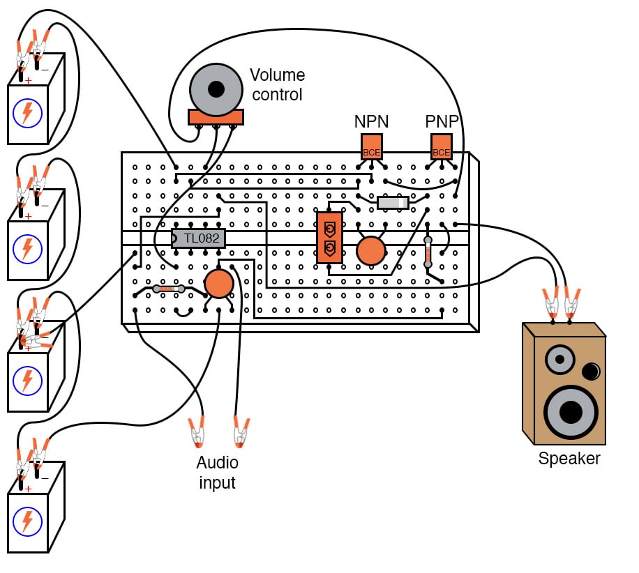
Figure 1. Breadboard implementation of an analog circuit—a Class B audio amplifier.
These experiments are designed to be easy for students, hobbyists, or makers to follow along.
Analog circuits are often referred to as linear circuits to emphasize the valid continuity of signal range forbidden in digital circuits, but this label is unfortunately misleading. Just because a voltage or current signal can vary smoothly between the extremes of zero and full power supply limits does not necessarily mean that all mathematical relationships between these signals are linear in the straight-line or proportional sense of the word. As you will see in this chapter, many so-called linear circuits are quite nonlinear in their behavior, either by the necessity of physics or by design.
The Operational Amplifier (Op Amp)
These projects will introduce you to the operational amplifier or op amp. The op amp is perhaps the most versatile and important analog IC for the student to master. Essentially nothing more than a differential amplifier with a very high voltage gain, op amps are the workhorse of the analog design world. By cleverly applying feedback from the output of an op amp to one or more of its inputs, as illustrated in the example of Figure 2, a wide variety of behaviors may be obtained from this single device.
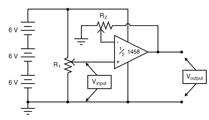
Figure 2. Schematic diagram of a non-inverting amplifier circuit using an operational amplifier and negative feedback.
Many different models of op amp are available at low cost, but circuits described in this chapter will incorporate commonly available op amp models.
In these projects, operational amplifiers will be used in building many circuits, including:
- Analog voltage comparator
- Voltage follower with a high-impedance input
- Non-inverting amplifier with controllable gain
- Analog integrator
- Pulse-width modulated power controller
- Class B audio amplifier
Analog Circuit Concepts
In the process of building and testing these analog circuits, you will be introduced to several important concepts:
- Open loop gain
- Negative feedback
- Distortion
- Loading
- Bias current compensation
- Oscillators
- And much more!