 Facebook
 Google
 GitHub
 Linkedin
Analog Lab - Precision Voltage Follower Using an Op Amp
Project Overview
The voltage follower is a simple but essential building block of many analog systems. As illustrated in Figure 1, an operational amplifier (op amp) with its output connected to its negative input is used to construct the voltage follower.
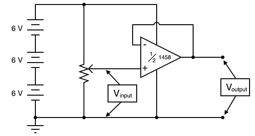
Figure 1. Schematic diagram of the op amp voltage follower circuit.
Parts and Materials
- Op amp, model 1458 or 353, recommended
- Three 6 V batteries or an 18 V power supply
- One 10 kΩ potentiometer, linear taper
Learning Objectives
- How to use an op amp as a voltage follower
- The purpose of negative feedback
- Illustrate some circuit troubleshooting strategy
Negative Feedback
In the voltage comparator experiment, the amplifier was used in open-loop mode, that is, without any feedback from output to input. As such, the full voltage gain of the op amp was available. This resulted in the output voltage saturating for virtually any amount of differential voltage applied between the two input terminals. This is good if we desire comparator operation, but if we want the op amp to behave as a true amplifier, we need it to exhibit a manageable voltage gain.
Since we do not have the luxury of disassembling the integrated circuitry of the op amp and changing resistor values to reduce the voltage gain, we are limited to external connections and componentry. Fortunately, this is not a disadvantage, as one might think! The combination of extremely high open-loop voltage gain coupled with feedback allows us to use the op amp for a much wider variety of purposes. Additionally, we can make system changes much easier than if we were to exercise the option of modifying its internal circuitry.
In the circuit of Figure 1, the output of the op amp is connected to its inverting (-) input. This is called negative feedback. With feedback, the op amp is now operating in a closed-loop mode.
Op Amp Voltage Follower Theory of Operation
To understand the operation, imagine if the voltage input on the non-inverting (+) input increases above the inverting (-) input. The high gain of the op amp will increase the output. This increased output is fed back to the inverting (-) input.
The output voltage will seek whatever level is necessary to balance the inverting (-) input’s voltage with that applied to the noninverting (+) input. If this feedback connection is direct, as in a straight piece of wire, the output voltage will precisely follow the noninverting input’s voltage.
Instructions
Step 1: Build the voltage follower circuit of Figure 1. A breadboard implementation of this circuit is illustrated in Figure 2.
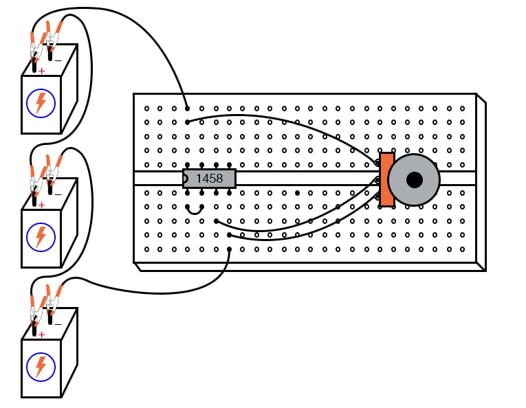
Figure 2. Breadboard implementation of the op amp voltage follower.
Step 2: Measure the input voltage of this circuit with a voltmeter connected between the op amp’s noninverting (+) input terminal and circuit ground (the negative side of the power supply).
Step 3: Measure the output voltage between the op amp’s output terminal and circuit ground. Is the output voltage the same as the input voltage?
Step 4: Watch the op amp’s output voltage follow the input voltage as you adjust the potentiometer through its range. You may directly measure the difference, or error, between output and input voltages by connecting the voltmeter between the op amp’s two input terminals. Throughout most of the potentiometer’s range, this error voltage should be almost zero.
Step 5: Try moving the potentiometer to one of its extreme positions, far clockwise or far counterclockwise. Measure the error voltage, or compare the output voltage against the input voltage. Do you notice anything unusual?
If you are using model 1458 or model 353 op amp for this experiment, you should measure a substantial error voltage or difference between output and input. Many op amps, the specified models included, cannot swing their output voltage exactly to full power supply (rail) voltage levels. In this case, the rail voltages are +18 volts and 0 volts, respectively.
Due to limitations in the 1458’s internal circuitry, its output voltage cannot exactly reach these high and low limits. You may find that it can only go within a volt or two of the power supply rails. This is a very important limitation to understand when designing circuits using operational amplifiers. If full rail-to-rail output voltage swing is required in a circuit design, other op amp models may be selected which offer this capability. The model 3130 is one such op amp.
Applications of Voltage Followers
Precision voltage follower circuits are useful if the voltage signal to be amplified cannot tolerate loading; that is if it has a high source impedance. Since a voltage follower, by definition, has a voltage gain of 1, its purpose has nothing to do with amplifying voltage but rather with amplifying a signal’s capacity to deliver current to a load.
Voltage follower circuits have another important use for circuit builders: they allow for simple linear testing of an op amp. One of the troubleshooting techniques I recommend is simplifying and rebuilding. Suppose that you are building a circuit using one or more op amps to perform some advanced function. If one of those op amps seems to be causing a problem and you suspect it may be faulty, try re-connecting it as a simple voltage follower and see if it functions in that capacity. An op amp that fails to work as a voltage follower certainly won’t work as anything more complex.
Op Amp Voltage Follower Equations
Let's walk through the derivation of the voltage follower gain equation, beginning from the op amp open-loop gain equation:
$$V_{out} = A \cdot (V_+ - V_-)$$
Where A is the open-loop gain of the op amp.
Since Vout is directly connected to V-, we can substitute Vout for V- and solve for Vout in terms of V+:
$$V_{out} = A \cdot (V_+ - V_{out})$$
$$V_{out} = AV_+ - AV_{out}$$
$$V_{out} +AV_{out}= AV_+$$
$$(1+A)V_{out}= AV_+$$
$$V_{out} = \left( \frac{A}{1+A} \right) V_+ $$
The op amp open-loop gain, A, is typically a very large number, at least 10,000, and often much more. Let's plug 10,000 into our equation:
$$V_{out} = \left( \frac{10,000}{1+10,000} \right) V_+ = 0.9999V_+$$
Therefore, the output error for the voltage follower is only 0.01% for an op amp with a gain of 10,000. Thus, we can call this a precision voltage follower. Unlike the voltage follower circuit made from a single transistor, which approximated the input voltage to within several tenths of a volt, this voltage follower circuit will output a voltage accurate to within mere microvolts of the input voltage.
SPICE Simulation of the Op Amp Voltage Follower
The circuit schematic of Figure 3 uses a dependent voltage source (E1) to simulate an op amp.
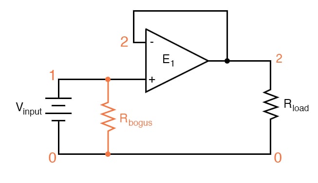
Figure 3. SPICE circuit schematic with node numbers for simulation of the op amp voltage follower circuit.
Netlist (make a text file containing the following text, verbatim):
Voltage follower
vinput 1 0
rbogus 1 0 1meg
e1 2 0 1 2 999meg
rload 2 0 10k
.dc vinput 5 5 1
.print dc v(1,0) v(2,0) v(1,2)
.end
An ideal operational amplifier may be simulated in SPICE using a dependent voltage source (e1 in the netlist). The output nodes are specified first (2 0) and then the two input nodes, with the non-inverting input first (1 2). The open-loop gain is specified last (999meg) in the dependent voltage source line.
Since SPICE views the input impedance of a dependent source as infinite, some finite amount of resistance must be included to avoid an analysis error. This is the purpose of Rbogus: to provide a DC path to the ground for the Vinput voltage source. Such “bogus” resistances should be arbitrarily large. In this simulation, I chose 1 MΩ for a Rbogus value.
A load resistor is included in the circuit for much the same reason: to provide a DC path for current at the output of the dependent voltage source. As you can see, SPICE doesn’t like open circuits!
Related Content
Learn more about the fundamentals behind this project in the resources below.
Textbook:
Worksheet:
- Op-amp Circuits Worksheet
- Basic Operational Amplifiers Worksheet
- Inverting and Non-inverting Op-amp Voltage Amplifier Circuits Worksheet


