Facebook
 Google
 GitHub
 Linkedin
Analog Lab - Voltage Comparator
Project Overview
In this project, you will build the analog comparator circuit, illustrated in Figure 1.
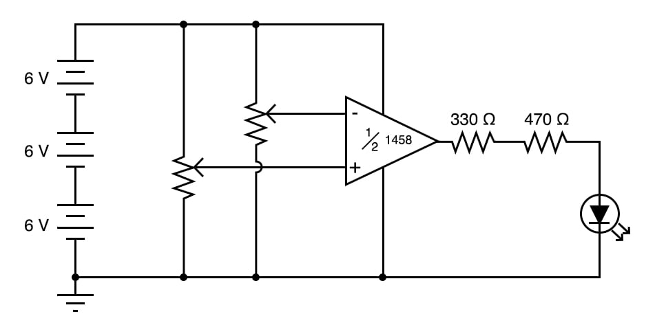
Figure 1. Schematic diagram of an analog comparator with LED indicator.
This analog comparator circuit uses an open-loop operational amplifier (op amp) to compare two voltage signals and determine which one is greater. The result of this comparison is indicated by the output voltage, which turns on or off a light-emitting diode (LED).
Parts and Materials
- Operational amplifier, model 1458 or 353, recommended
- Three 6 V batteries or an 18 V power supply
- Two 10 kΩ potentiometers, linear taper
- One LED
- One 330 Ω resistor
- One 470 Ω resistor
This experiment only requires a single op amp. The models 1458 and 353 are both dual op amp units, with two complete amplifier circuits housed in the same 8-pin DIP package.
I recommend that you purchase and use dual op amps over single op amps even if a project only requires one because they are more versatile (the same op amp unit can function in projects requiring only one amplifier as well as in projects requiring two). In the interest of purchasing and stocking the least number of components for your home laboratory, this makes sense.
Learning Objectives
- How to use an op amp as a comparator
- Understand the open-loop operation of an op amp
Analog Comparator Theory of Operation
As illustrated in the schematic diagram of Figure 1, the two potentiometers are used to adjust the positive and negative input voltages of the op amp. The op amp compares these two input values and outputs either a high or low voltage based on the following relationships:
$$V_+ - V_- > 0 \text{ then } V_{out} = \text{ high}$$
$$V_+ - V_- < 0 \text{ then } V_{out} = \text{ low}$$
The open-loop output voltage of the op amp is given by:
$$V_{out} = Gain \cdot (V_+ - V_-)$$
Open-loop means that there is no feedback from the op amp output to either of its inputs. Op amps have very high open-loop gain, often on the order of 10,000 or more. Therefore, even a small difference in the input voltages will typically result in the op amp output saturating at either its high or low limits near the upper and lower supply voltages, respectively.
The output status of the op amp is indicated visually by the LED. When the op amp output is high, the LED will be forward-biased and turn on. When the op amp output is low, the LED will be reverse-biased and turn off.
Instructions
Step 1: Build the op amp circuit illustrated in Figures 1 and 2.
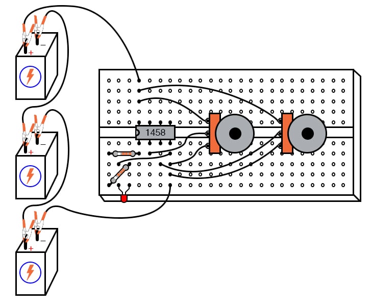
Figure 2. Breadboard implementation of the analog comparator with LED indicator.
The resistors connected to the output of the op amp limit the current through the LED.
Step 2: Adjust the two potentiometers and observe the LED. From this, you should be able to easily confirm the function of the op amp comparator circuit as described above.
Step 3: For greater insight into this circuit’s operation, you might want to connect a pair of voltmeters to the op amp input terminals (both voltmeters referenced to ground), as illustrated in Figure 3.
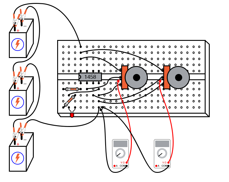
Figure 3. Measuring the operational amplifier input voltages created by the potentiometers.
This will allow you to numerically compare both input voltages and then compare the expected output with the LED status.
Applications of Analog Comparators
Comparator circuits are widely used to compare and monitor physical measurements, provided those physical variables can be translated into voltage signals. For instance, if a small generator were attached to an anemometer wheel to produce a voltage proportional to wind speed, as shown in Figure 4.
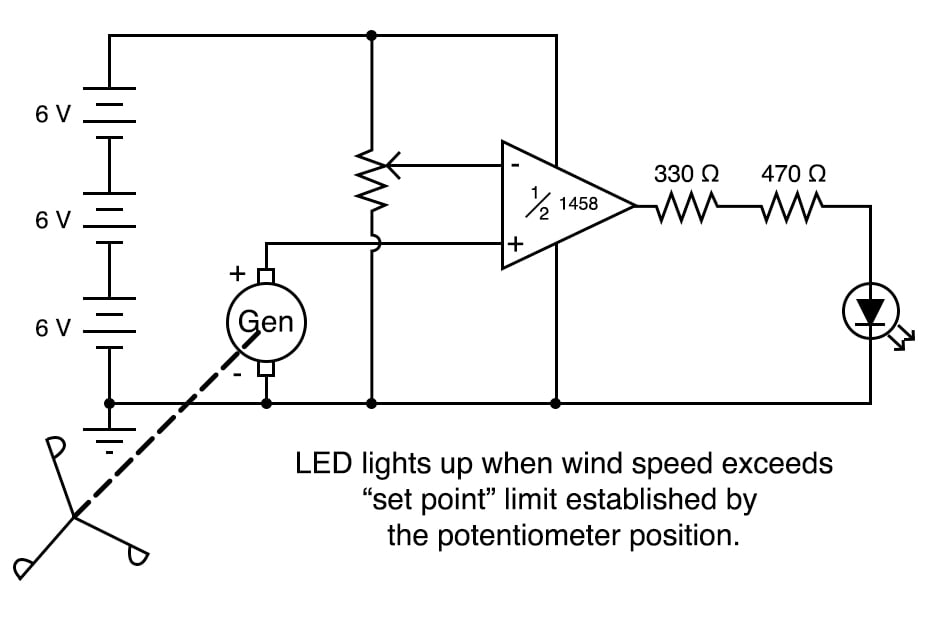
Figure 4. Example application of an analog comparator.
That wind speed signal could be compared with a set-point, high-limit voltage. The output of the op amp could then drive a high wind speed alarm.
Related Content
Learn more about the fundamentals behind this project in the resources below.
Textbook:
Worksheet: