Facebook
 Google
 GitHub
 Linkedin
Beyond PLL Lock: Rethinking AC Phase Timing Confidence
PLL lock doesn't mean your phase timing is trustworthy. Learn why AC synchronization systems need measured, validated phase references—not just loop convergence.
AC-synchronized power-conversion systems depend on accurate phase timing. In grid-connected inverters, motor drives, solid-state power controllers, and other line-synchronized equipment, the controller often needs to answer a simple question very quickly: where are we in the AC cycle right now?
That answer affects current injection, switching updates, sampling, and protection decisions. If the phase reference is correct, the control system has a stable timing foundation. If it is wrong, the controller may still appear normal while making decisions from incorrect timing information.
That distinction matters because a synchronization circuit can appear to be working while still producing a questionable phase reference.
A phase-locked loop, or PLL, is a common way to create an AC phase reference. In many applications, PLLs work well. They can smooth noise, track frequency, and provide a continuously updated estimate of phase. However, a PLL is still an estimating system. It does not directly prove that the waveform being followed is healthy, symmetrical, or safe to use as a timing reference.
A PLL can appear locked while the phase information it produces is not as trustworthy as the word "locked" might suggest.
Zero Crossings Are Not Enough
Many AC synchronization systems begin with the zero crossing. That makes sense: the zero crossing is easy to detect, repeats every half-cycle, and provides a convenient reference point for timing. But a zero crossing alone does not prove that the AC waveform is healthy.
Compare the imbalanced AC waveform at the right side of Figure 1 to the normal waveform at left. The positive half-cycle and negative half-cycle in the imbalanced signal are not the same duration. The waveform still crosses zero.
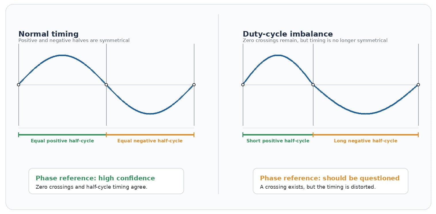
Figure 1. A zero crossing can still be present even when the positive and negative half-cycle timing is no longer symmetrical. [click to enlarge]
A zero-cross detector may still produce a clean-looking pulse. A downstream synchronization system may still report that it is tracking. Yet the timing of the positive and negative halves is no longer symmetrical. Therefore, the timing confidence is different.
This type of duty-cycle imbalance can come from:
- Distortion
- Asymmetrical loading
- Measurement imperfections
- Local power-system behavior
- Equipment interaction.
The key point is that the zero crossing can continue to occur even when the timing implied by that crossing is not a stable or fully trustworthy phase reference.
The Problem With False Phase Confidence
The issue is not simply that a PLL can have error. All practical synchronization systems have some error. The more serious issue is false confidence: the system may treat the phase reference as valid even when the underlying waveform timing is questionable.
A PLL does not know the engineer's intent. It follows the signal presented to it according to its loop design, filtering, bandwidth, and control behavior. If the signal contains distortion or timing imbalance, the PLL may generate a phase estimate that is smooth and continuous, but not necessarily correct for the control decision being made.
That can become especially important in systems containing many DC-AC inverters. Each inverter may be synchronizing to the same AC line while also changing that line slightly through its own current injection. In a weak or stressed system, the relationship between inverter current and local voltage can become significant.
A simplified feedback pattern can develop: the inverter reads a phase estimate, adjusts current, changes the local AC waveform, then reads the changed waveform and adjusts again. Under the wrong conditions, this can contribute to low-frequency hunting, subharmonic behavior, or other line distortion.
The distortion may come from many systems making small timing decisions from phase information that was accepted as valid when it should have been questioned.
This is the core engineering concern: incorrect phase information can lead to incorrect current timing, and incorrect current timing can create or reinforce unwanted distortion on the AC line.
PLL Lock Is Not the Same as Timing Validity
The word "lock" can be misleading. In a PLL-based system, lock usually means the loop has reached a condition where its internal phase and frequency behavior are within expected limits. That is useful information, but it is not the same as saying the incoming waveform is suitable for every downstream control decision.
A controller designer may need a stronger question answered: Is this phase reference valid enough to act on right now?
That question is different from asking whether a loop has settled or whether a zero crossing was detected. A high-confidence timing reference should be based on measured cycle behavior, should reject timing that does not meet validity requirements, and should recover quickly when the waveform becomes usable again.
For AC-synchronized control systems, phase confidence should be treated as a design requirement, not just a byproduct of lock detection.
The Phase Engine Solution: Measured, Validated Phase Timing
The patented Phase Engine is not just another way to smooth or filter a phase estimate. Its purpose is to create a usable AC phase timeline from direct measurement of the waveform timing, while also helping the controller decide whether that timing should be trusted.
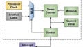
Let’s examine the differences between a conventional PLL path and the Phase Engine path as illustrated in Figure 2.
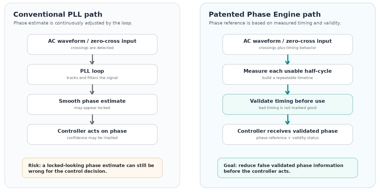
Figure 2. A conventional PLL path compared to a Phase Engine path that adds measured timing and validity before the controller acts. [click to enlarge]
Instead of depending on a conventional PLL loop to chase the incoming waveform, the Phase Engine measures each usable half-cycle and builds a phase timeline from that interval. The controller can then act from the waveform period that actually occurred, not from an estimate that may have been pulled by distortion, imbalance, or interaction with other equipment.
Just as important, the Phase Engine is designed around timing validity. When the waveform timing is usable, it can provide a repeatable phase reference. When timing is questionable, the system can avoid presenting bad phase information as if it were good.
The central value of the Phase Engine is that it reduces the likelihood of false validated phase information.
A conventional PLL path can imply confidence from loop behavior. A Phase Engine path adds measured timing and validity before the controller acts
This does not mean the Phase Engine makes a bad AC waveform clean. No synchronization circuit can do that. The goal is more practical: prevent the control system from confidently acting on phase timing that should not have been trusted.
In power electronics, a wrong answer marked "valid" can be more dangerous than no answer at all. The Phase Engine is intended to give the controller a better choice: use the phase reference when the timing is valid, and withhold confidence when the timing is not valid.
Why Fast Recovery Matters
A synchronization system should not only detect bad timing. It should also recover quickly when good timing returns.
In many AC systems, disturbances are temporary. A load changes, a transient occurs, a distorted cycle passes, and then the waveform becomes usable again. If the phase reference takes many cycles to settle, the controller may be forced to wait or operate conservatively.
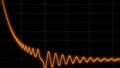
However, if valid timing can be re-established on the next usable cycle, the controller can return to normal operation more quickly. This is demonstrated in Figure 3.
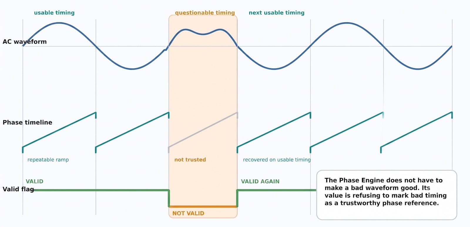
Figure 3. The desired behavior is to use valid timing, withhold questionable timing, and recover when the next usable cycle is measured. [click to enlarge]
This is valuable for systems that make time-sensitive decisions. Current injection, switch timing, sampling windows, and protection thresholds can all depend on knowing where the controller is in the AC cycle. A timing architecture that quickly rejects bad information and revalidates good information gives the higher-level controller better data.
Reducing the Chance of Reinforced Line Distortion
The need for phase confidence grows as more inverter-based systems operate together. Solar inverters, energy-storage systems, variable-speed drives, smart loads, and other power electronic equipment increasingly share the same electrical infrastructure. They may see the same line conditions and respond to the same disturbances.
If multiple systems rely on phase references that can accept questionable timing as valid, their responses can become correlated. One unit's timing error may be small. Many units responding to the same distorted phase information can be more serious.
That is why the issue is not limited to one inverter. It can become a system-level concern. Bad phase information can affect current timing. Current timing can affect the AC line. The changed AC line can then affect other synchronization systems connected to it.
A synchronization architecture that reduces false valid phase information helps break that chain. It does not need to solve every grid-stability problem to be useful. It only needs to reduce one important failure mode: acting on phase timing that should not have been trusted.
Synchronization With Confidence
Conventional PLLs remain useful tools, but PLL lock should not be treated as proof that phase timing is correct for every AC-synchronized control decision. A waveform can still cross zero while its timing is distorted. A loop can still appear locked while the phase information it produces is not ideal for current timing, sampling, switching, or protection.
The goal is not simply synchronization. The goal is synchronization with confidence.
As more inverter-based systems operate together on shared AC lines, phase-information quality becomes more important. Incorrect phase information can cause incorrect current timing. Incorrect current timing can create or reinforce unwanted distortion. With multiple power-conversion systems on the same line, that distortion can become a broader system-level problem.
The Phase Engine is offered as a solution to that specific failure mode. It is designed to create a measured, repeatable AC phase timeline and reduce the chance that questionable timing is accepted as valid. Instead of asking the controller to trust a phase estimate because a loop appears locked, the Phase Engine gives the controller a clearer basis for deciding when the phase reference should be used.
For future inverter and power-conversion designs, the engineering question should not be only, "Is the PLL locked?" The better question is, "Is the phase timing trustworthy enough to act on?" That is the purpose of the Phase Engine.
Related Content