 Facebook
 Google
 GitHub
 Linkedin
Applications of the Op-Amp: Voltage Follower Circuit
The operational amplifier is a versatile, user-friendly component that has been incorporated into an endless variety of circuits and applications. One reason for the op-amp’s popularity is its ability to combine simplicity and performance: op-amp circuits are a valuable addition to many types of systems, yet they are not difficult to design and often require very few external components.
In this video, we’ll be exploring the voltage follower, which is a good example of an op-amp circuit that is simple yet very useful.
The Op-Amp Voltage Follower
The most basic form of the voltage follower, also called a unity-gain buffer, is shown in the diagram below.
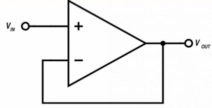
As you can see, the only necessary component is the op-amp itself (however, you do need a decoupling capacitor for the IC’s power supply).
A voltage follower produces an output signal that is equal in amplitude to the input signal. Because the input signal is applied to the noninverting input terminal, no inversion takes place. Thus, the voltage follower is a noninverting buffer.
The unity-gain operation of the voltage follower is achieved by means of negative feedback. The input signal is applied to the op-amp’s noninverting input terminal, and the output terminal is connected directly to the inverting input terminal.
If the operational amplifier were operating as an open-loop amplifier (that is, without negative feedback), a small increase in the input voltage would cause a large increase in the output voltage, because the op-amp has very high gain.
The negative-feedback connection creates a compensating effect: it returns this increased output voltage to the negative portion of the differential input stage, and consequently, the output voltage decreases. The overall effect of negative feedback in the voltage follower is to cause the output voltage to settle on a value that is equal to the voltage at the noninverting input terminal.
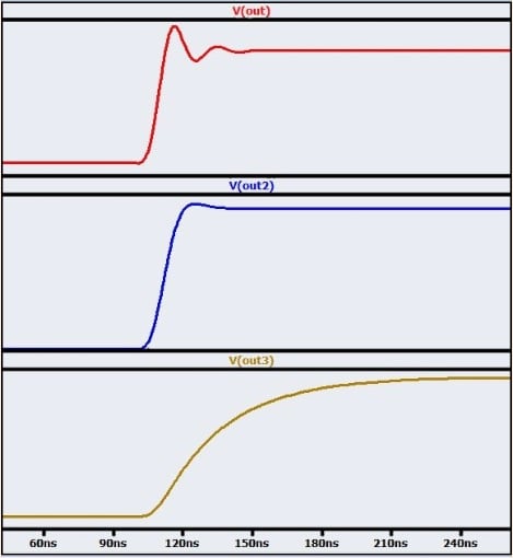
When the input signal has variations that are slow relative to the op-amp’s dynamic performance, we don’t notice this settling action. We simply observe an output signal that is the same as the input signal. However, the settling action is apparent when we apply a rapid transition to the voltage follower.
The plot below gives you three examples of what this settling behavior might look like.
Reasons for Using a Voltage Follower
A voltage follower does not increase or decrease the amplitude of the input signal, and it does not filter out high-frequency noise. Thus, you might be wondering why a circuit like this is so useful. It is true that a voltage follower does not intentionally alter the amplitude or frequency characteristics of the input signal, but it does allow us to improve impedance relationships.
Whenever we are sending a voltage signal from one subcircuit to another, we have to consider the output impedance of the source subcircuit and the input impedance of the load subcircuit.
The source’s output impedance and the load’s input impedance form a voltage divider, and consequently, voltage transfer depends on the ratio of input impedance to output impedance. Effective voltage transfer requires a source circuit with low output impedance and a load circuit with high input impedance.
A voltage follower has low output impedance and extremely high input impedance, and this makes it a simple and effective solution to problematic impedance relationships. If a high-output-impedance subcircuit must transfer a signal to a low-input-impedance subcircuit, a voltage follower placed between these two subcircuits will ensure that the full voltage is delivered to the load.
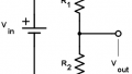
One example of a simple but important voltage-follower application is the circuit shown below.
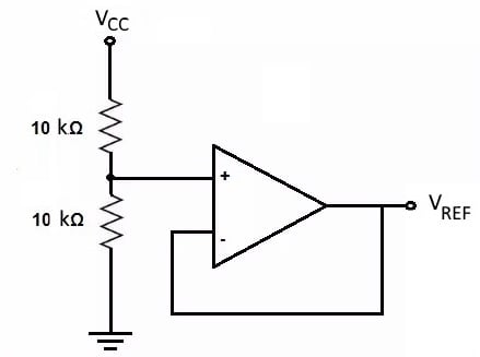
A reference voltage (\(V_{REF}\)) can be generated using a resistive voltage divider, but the circuit’s output impedance will not be low, especially if higher-value resistors are used as a way of reducing current consumption. The voltage follower is not negatively affected by the divider’s output impedance, and it produces a low-output-impedance reference voltage for other components in the system.
Voltage Follower Stability
In general, you can rely on a voltage follower to do exactly what the name suggests, i.e., create an output signal that follows the input signal. However, there is one serious failure mode that every circuit designer needs to be aware of. The problem here is stability—the voltage follower, like other types of op-amp circuits, is susceptible to oscillation.
Oscillation in negative-feedback amplifiers is related to phase shift that causes negative feedback to become positive feedback. You might think that a voltage follower would not have stability problems because the circuit has no overall amplification, but in fact, voltage followers are more susceptible to oscillation than circuits with higher gain. (For more information on this interesting but somewhat complicated topic, please refer to AAC’s article on gain margin and phase margin.)
In most cases, all that you need to do to prevent oscillation in your voltage follower is to choose an op-amp that is described as “unity-gain stable.” These op-amps are internally compensated in such a way as to create a frequency response that allows for stable operation even when the device is used in a voltage-follower configuration.
A High-Current Voltage Follower
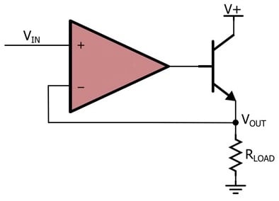
The voltage follower’s low output impedance makes it a good circuit for driving current into a low-impedance load, but it’s important to remember that most op-amps are not designed to deliver large output currents.
You can create a high-current version of the voltage follower using the configuration shown in the diagram below (refer to this article for more information).
Summary
- A voltage follower is a unity-gain, noninverting buffer that requires only an operational amplifier (and a decoupling capacitor).
- Voltage followers have high input impedance and low output impedance—this is the essence of their buffering action. They strengthen a signal and thereby allow a high-impedance source to drive a low-impedance load.
- An op-amp used in a voltage-follower configuration must be specified as “unity-gain stable.”
- A high-current unity-gain driver can be created by incorporating an external transistor into the voltage-follower configuration.
Related Content


Hi nice video. What do you mean impedenca relation ? Could you give an example for this notion.
See more at the following link about high voltage operational amplifier.
https://tecseteletronica.blogspot.com/2025/05/o-adhv4710-uma-analise-detalhada-do.html