Facebook
 Google
 GitHub
 Linkedin
Transimpedance Amplifier: Op-Amp-Based Current-to-Voltage Signal Converter
We usually think of an amplifier as something that receives an input voltage and produces a higher-amplitude output voltage. However, an important variation on this basic amplification scheme involves conversion from current to voltage.
The current-to-voltage amplifier can be described as having a gain, because the output amplitude is equal to the input amplitude multiplied by a number chosen by the designer, but it’s a different type of gain because the output signal and the input signal have different units and therefore cannot be directly compared.
The Transimpedance Amplifier
A current-to-voltage amplifier is also called a transimpedance, or transresistance amplifier, and this reminds us that the circuit is performing the same basic function as a resistor. We know from Ohm’s law that voltage is equal to current times resistance, and in fact, an ordinary resistor can be used as a current-to-voltage converter—if you connect a resistor to a current source, the resistor will generate a voltage that is equal to the current multiplied by the “gain,” i.e., the resistance.
The following diagram conveys the most basic form of the op-amp transimpedance amplifier.
![]()
At this point, you might be wondering why we need an op-amp for current-to-voltage conversion if the task can be accomplished by a single resistor, and this diagram will help us to understand the advantages of the transimpedance amplifier circuit.
Understanding Transimpedance Amplifier Operation
First, we have to remember two important techniques that we use to simplify the analysis of negative-feedback op-amp circuits: we can assume 1) that no current flows into the op-amp’s inputs and 2) that the voltage at the noninverting input terminal is equal to the voltage at the inverting input terminal (this is called the virtual short).
- Since no current enters the inverting input terminal, all of the input current flows through the feedback resistor (\(R_F\)) on its way to the output node.
- The noninverting input terminal is connected to ground, and therefore we can assume that the inverting input terminal is also at ground.
- Since one side of the feedback resistor is at (virtual) ground and the other side is connected to \(V_{OUT}\), all we need is Ohm’s law to tell us that the magnitude of the output voltage is equal to the input current times the feedback resistance.
The input-to-output relationship of the op-amp transimpedance amplifier is expressed as follows: \( V_{OUT} = - I_{IN} \times R_F \). The negative sign in this equation is an important detail. If current is flowing into the circuit, the voltage across the feedback resistor will have polarity as shown in the following diagram:
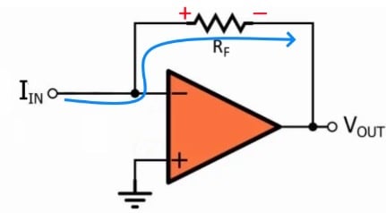
The right-hand terminal of the resistor is at a lower potential than the left-hand terminal, and since the left-hand terminal is at (virtual) ground, the output voltage will be negative.
Transimpedance Amplifier vs. Resistor
The transimpedance amplifier has the same gain as an ordinary resistor, but it is a much better method of current-to-voltage conversion, because the impedance characteristics are far superior.
When we are attempting to transfer a voltage signal, we want an amplifier with high input impedance, because this reduces the amount of voltage that is lost across the source’s output impedance. It’s important to remember, though, that the opposite situation occurs when we want to transfer a current signal; in this case, the input impedance should be as low as possible.
Since the transimpedance amplifier’s inverting input terminal is connected to ground through the virtual short, the input impedance is essentially zero, even when we use a very large feedback resistance in order to achieve a very high gain. This is in stark contrast to an ordinary resistor, where input impedance is equal to resistance and therefore very high gain corresponds to very high input impedance.
The transimpedance amplifier is also superior in terms of output impedance. If we use nothing but a resistor to perform current-to-voltage conversion and then connect a load resistor across the current-to-voltage resistor, we have two resistors in parallel, and the gain becomes the equivalent resistance. Thus, if we use a large resistor to achieve high gain and then connect a much smaller load resistor, the gain decreases dramatically.
The transimpedance amplifier, on the other hand, exhibits the low output impedance that we expect from any op-amp circuit.
Transimpedance Amplifier Stability
Op-amp-based transimpedance amplifiers are frequently used to amplify current signals generated by photodiodes. These implementations are susceptible to oscillation problems caused by the photodiode’s junction capacitance; this capacitance is shown in the diagram below, where the photodiode has been replaced by an equivalent circuit.
![]()
We can make photodiode amplifiers stable by including a compensation capacitor that is connected in parallel with the feedback resistance. For more information on this topic, please refer to AAC’s article on transimpedance amplifier stability.
Summary
- The transimpedance amplifier uses an op-amp and a feedback resistor to generate an output voltage that is proportional to an input current.
- The magnitude of the gain is equal to the feedback resistance, and since inversion occurs, the circuit’s transfer function is \( V_{OUT} = - I_{IN} \times R_F \).
- Like a resistor, a transimpedance amplifier converts current to voltage, but unlike a resistor, it has low input impedance and low output impedance even with very high gain.
- A compensation capacitor connected in parallel with the feedback resistor is used to ensure stability in photodiode applications.
Related Content