Facebook
 Google
 GitHub
 Linkedin
Negative Feedback in Op-Amps
A previous video tutorial presented an idealized op-amp model in which the inputs have infinite impedance and the difference between the two input voltages is multiplied by an infinite gain and delivered via zero resistance to the output terminal, without any loss of performance as input frequency increases.
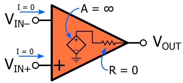
This model is a major simplification, because in real op-amps
- the gain is high but definitely not infinity,
- the output resistance is fairly low but definitely not zero,
- input currents are required for operation, and
- the gain usually begins to decrease at a low frequency.
However, it’s important to understand that the idealized model is not intended to exist in isolation because op-amps are not intended to be used as “open-loop” amplifiers. Rather, we almost always incorporate op-amps into a “closed-loop” configuration—that is, a configuration in which negative feedback creates a continuous signal path from the input to the output and back to the input.
What Is Negative Feedback?
The term “feedback” refers to taking an output signal, or a portion of an output signal, and returning it (i.e., feeding it back) to the system’s input. Feedback can be negative or positive, but negative feedback is much more common. We create negative feedback by taking the output signal, or a portion of the output signal, and combining it with the input signal via subtraction.
(For a thorough exploration of this topic, please refer to AAC’s Negative Feedback series.)
This simple technique can transform an op-amp into an easy-to-use, versatile component that is more consistent with its idealized model.
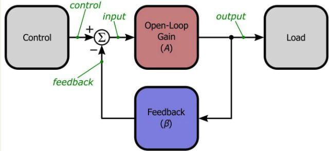
Gain and Feedback Factor
As you can see in the diagram above, the critical parameters in a feedback system are the open-loop gain (A) and the feedback factor (β). The feedback factor corresponds to the portion of the output that is fed back to the input. For example:
- If the output amplitude is reduced by half before it is fed back, β = 0.5.
- If 25% of the output amplitude is fed back, β = 0.25.
- If the output is connected directly to the input stage, β = 1.
The overall gain of the negative-feedback system, called the closed-loop gain (\(GCL \)), is calculated as follows:
\[G_{CL} = \frac {A}{1+A\beta}\]
However, if we assume that A is very large, we can make an important simplification in this formula:
\[G_{CL} \approx \frac {1}{\beta}\]
This tells us that as long as the amplifier’s open-loop gain is very high, the overall gain of the system is determined by the components that are used to reduce the amplitude of the output signal before it is fed back to the input.
Negative Feedback with Op-Amps
Op-amps make it very easy for us to create high-performance negative-feedback amplifier systems: subtraction is achieved by connecting the feedback signal to the inverting input terminal, and the op-amp’s extremely high gain allows us to use the simplified \(G_{CL} \) expression without worrying about the difference between the exact closed-loop gain and the approximate closed-loop gain. (For example, if A = 105 and β = 0.5, the approximate \(G_{CL} \) is 2 and the exact \(GCL \) is 1.99996.)
At this point, we are almost ready to design an op-amp-based negative-feedback amplifier. We know that the overall gain will be equal to the inverse of the feedback factor, but how do we create the feedback factor?
As explained above, the feedback factor corresponds to a reduction in the amplitude of the output signal, and we can reduce the amplitude of a signal simply by adding a pair of resistors:
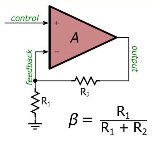
Here we are using a basic resistive voltage divider to create a feedback factor of \( \beta = R_1/(R_1+R_2) \). If, for example, we have \( R_1 = R_2 = 1 k\Omega \), β = 0.5, and this would result in an amplifier with an overall gain of \(G_{CL} = 2 \). We can easily adjust the gain by choosing different resistance values, and if necessary we can make the gain very accurate by using high-precision resistors.
Summary
- We create negative feedback by taking all or part of a system’s output signal and subtracting it from the input signal.
- If we build a negative-feedback system around a high-gain amplifier, the overall gain depends only on the feedback factor.
- We can design high-performance amplifiers by combining an op-amp with a resistive feedback network that reduces the amplitude of the output signal before feeding it back to the input.