Facebook
 Google
 GitHub
 Linkedin
Characteristic Impedance
The Parallel Wires of Infinite Length
Suppose, though, that we had a set of parallel wires of infinite length, with no lamp at the end. What would happen when we close the switch? Being that there is no longer a load at the end of the wires, this circuit is open. Would there be no current at all? (Figure below)
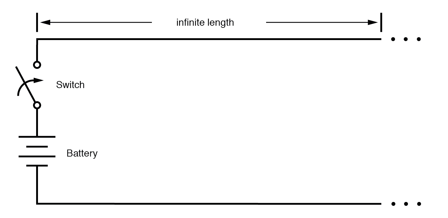
Driving an infinite transmission line.
Despite being able to avoid wire resistance through the use of superconductors in this “thought experiment,” we cannot eliminate capacitance along the wires’ lengths. Any pair of conductors separated by an insulating medium creates capacitance between those conductors: (Figure below)
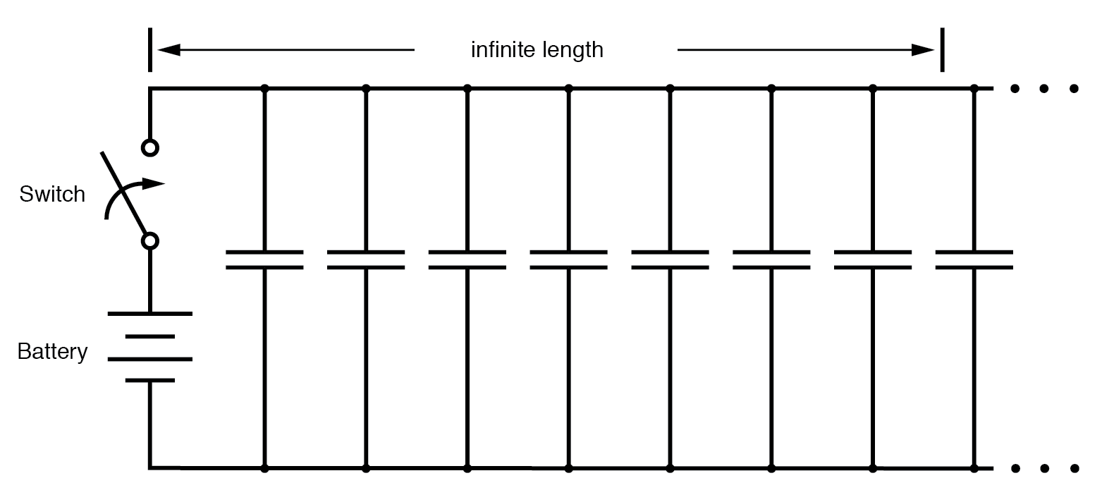
Equivalent circuit showing stray capacitance between conductors.
Voltage applied between two conductors creates an electric field between those conductors. Energy is stored in this electric field, and this storage of energy results in an opposition to change in voltage. The reaction of a capacitance against changes in voltage is described by the equation i = C(de/dt), which tells us that current will be drawn proportional to the voltage’s rate of change over time. Thus, when the switch is closed, the capacitance between the conductors will react against the sudden voltage increase by charging up and drawing current from the source. According to the equation, an instant rise in applied voltage (as produced by perfect switch closure) gives rise to an infinite charging current.
Capacitance and Inductance
However, the current drawn by a pair of parallel wires will not be infinite, because there exists a series of impedance along the wires due to inductance. (Figure below) Remember that current through any conductor develops a magnetic field of proportional magnitude. Energy is stored in this magnetic field, (Figure below) and this storage of energy results in an opposition to change in current. Each wire develops a magnetic field as it carries charging current for the capacitance between the wires, and in so doing drops voltage according to the inductance equation e = L(di/dt). This voltage drop limits the voltage rate-of-change across the distributed capacitance, preventing the current from ever reaching an infinite magnitude:
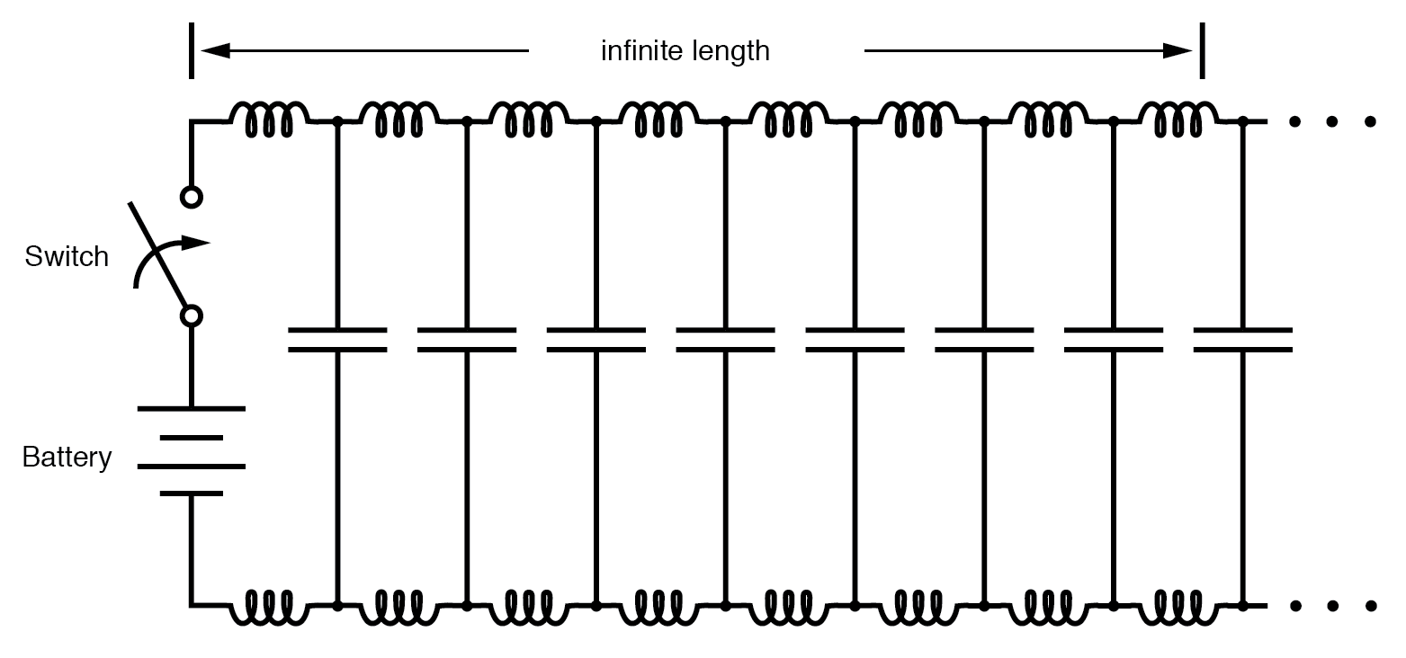
Equivalent circuit showing stray capacitance and inductance.
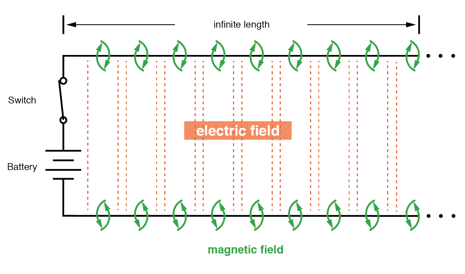
Voltage charges capacitance, current charges inductance.
Because the electric charge carriers in the two wires transfer motion to and from each other at nearly the speed of light, the “wave front” of voltage and current change will propagate down the length of the wires at that same velocity, resulting in the distributed capacitance and inductance progressively charging to full voltage and current, respectively, like this:
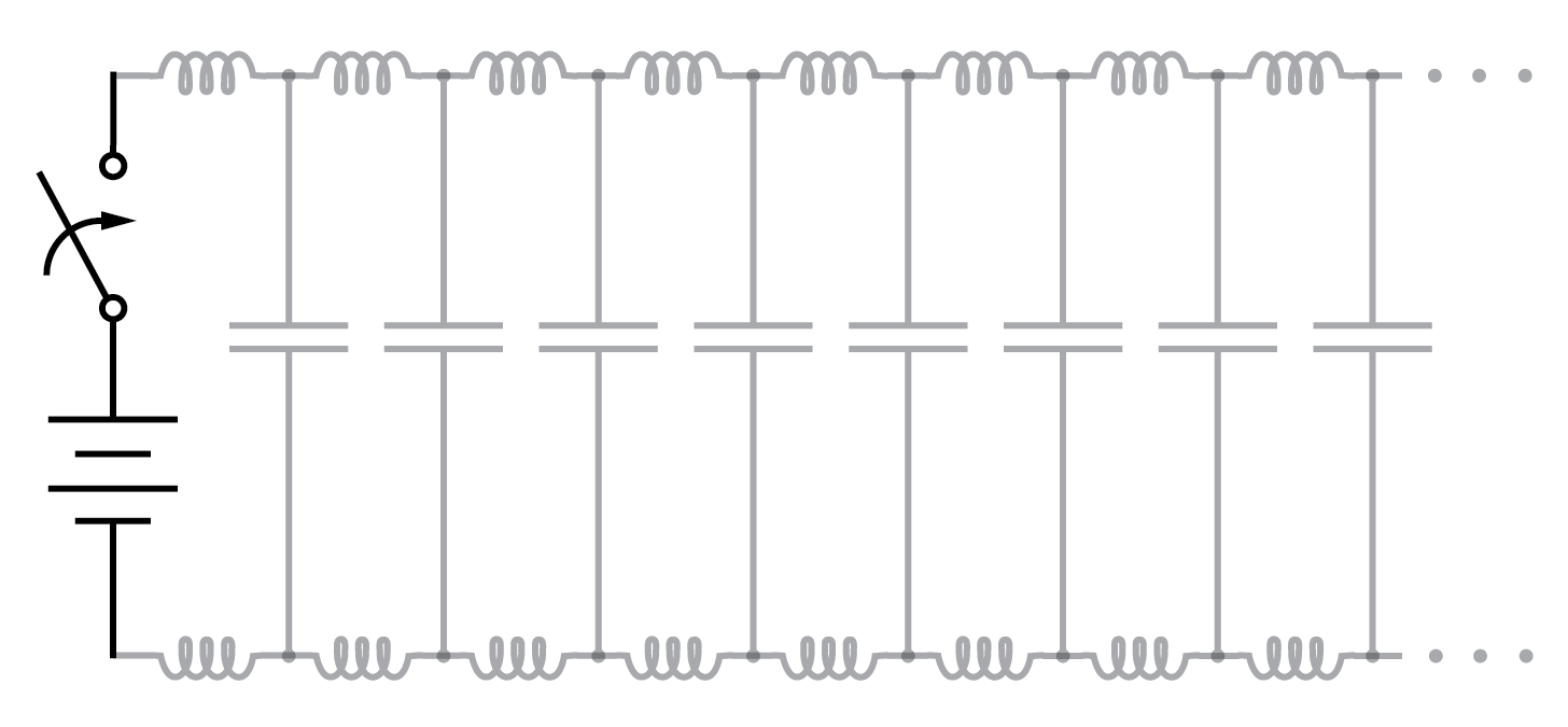
Uncharged transmission line.
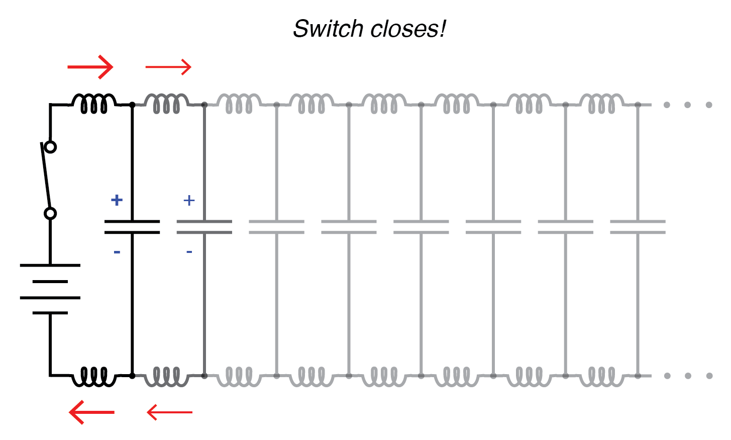
Begin wave propagation.
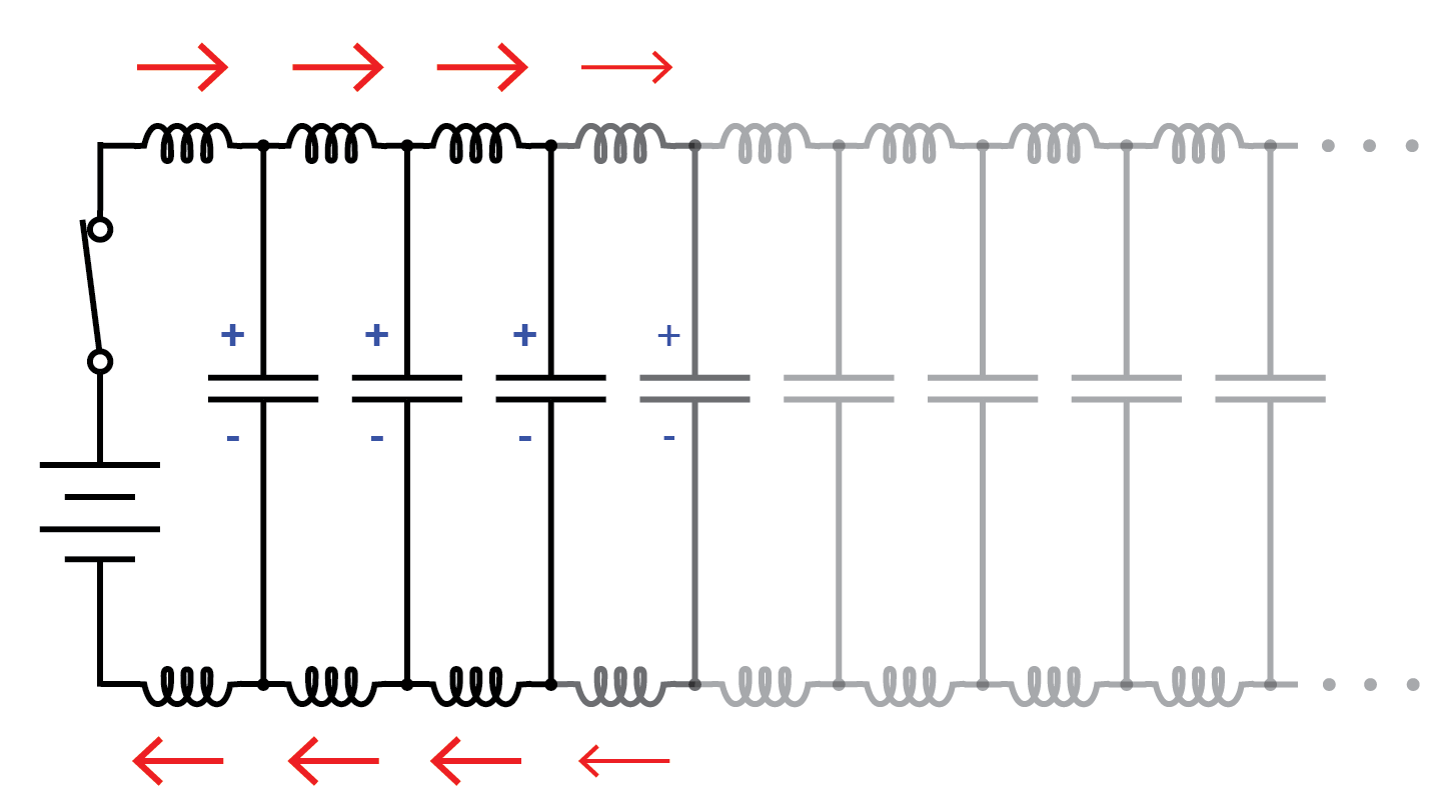
Continue wave propagation.
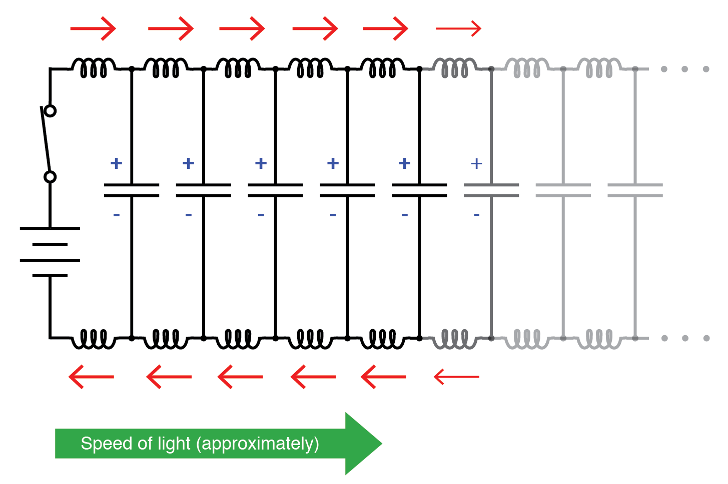
Propagate at speed of light.
The Transmission Line
The end result of these interactions is a constant current of limited magnitude through the battery source. Since the wires are infinitely long, their distributed capacitance will never fully charge to the source voltage, and their distributed inductance will never allow unlimited charging current. In other words, this pair of wires will draw current from the source so long as the switch is closed, behaving as a constant load. No longer are the wires merely conductors of electrical current and carriers of voltage, but now constitute a circuit component in themselves, with unique characteristics. No longer are the two wires merely a pair of conductors, but rather a transmission line.
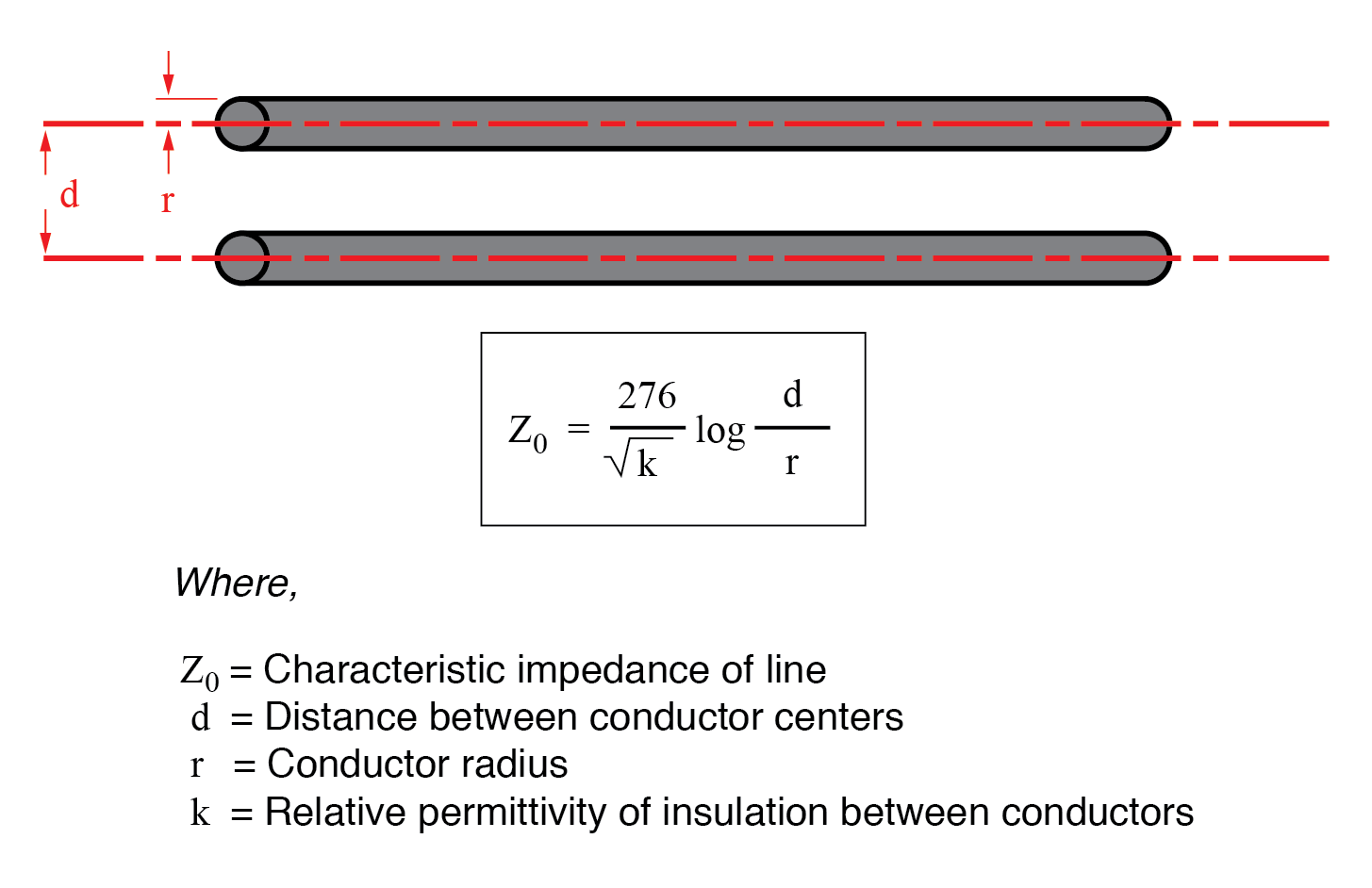
As a constant load, the transmission line’s response to the applied voltage is resistive rather than reactive, despite being comprised purely of inductance and capacitance (assuming superconducting wires with zero resistance). We can say this because there is no difference from the battery’s perspective between a resistor eternally dissipating energy and an infinite transmission line eternally absorbing energy. The impedance (resistance) of this line in ohms is called the characteristic impedance, and it is fixed by the geometry of the two conductors. For a parallel-wire line with air insulation, the characteristic impedance may be calculated as such:
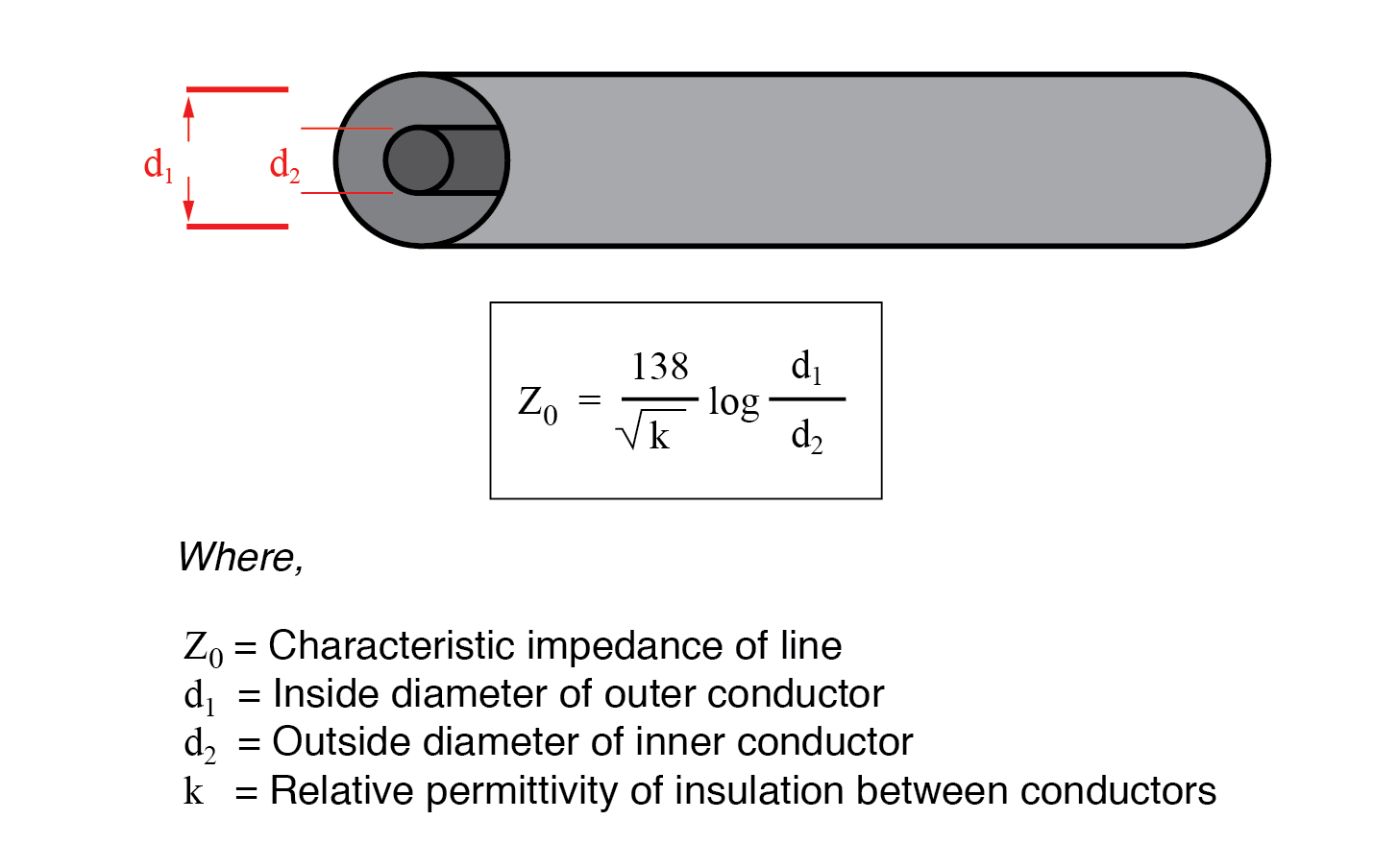
If the transmission line is coaxial in construction, the characteristic impedance follows a different equation:
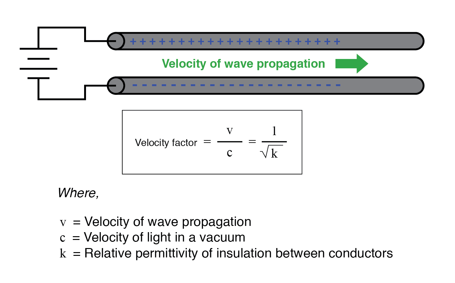
In both equations, identical units of measurement must be used in both terms of the fraction. If the insulating material is other than air (or a vacuum), both the characteristic impedance and the propagation velocity will be affected. The ratio of a transmission line’s true propagation velocity and the speed of light in a vacuum is called the velocity factor of that line.
Velocity factor is purely a factor of the insulating material’s relative permittivity (otherwise known as its dielectric constant), defined as the ratio of a material’s electric field permittivity to that of a pure vacuum. The velocity factor of any cable type—coaxial or otherwise—may be calculated quite simply by the following formula:
The Natural Impedance
Characteristic impedance is also known as natural impedance, and it refers to the equivalent resistance of a transmission line if it were infinitely long, owing to distributed capacitance and inductance as the voltage and current “waves” propagate along its length at a propagation velocity equal to some large fraction of light speed.
It can be seen in either of the first two equations that a transmission line’s characteristic impedance (Z0) increases as the conductor spacing increases. If the conductors are moved away from each other, the distributed capacitance will decrease (greater spacing between capacitor “plates”), and the distributed inductance will increase (less cancellation of the two opposing magnetic fields). Less parallel capacitance and more series inductance result in a smaller current drawn by the line for any given amount of applied voltage, which by definition is a greater impedance. Conversely, bringing the two conductors closer together increases the parallel capacitance and decreases the series inductance. Both changes result in a larger current drawn for a given applied voltage, equating to a lesser impedance.
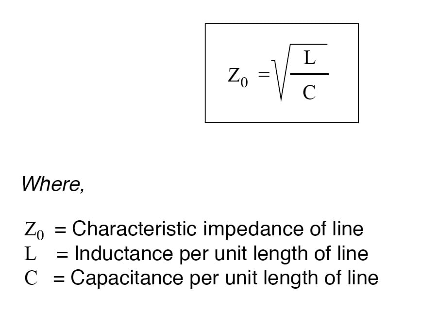
Barring any dissipative effects such as dielectric “leakage” and conductor resistance, the characteristic impedance of a transmission line is equal to the square root of the ratio of the line’s inductance per unit length divided by the line’s capacitance per unit length:
REVIEW:
- A transmission line is a pair of parallel conductors exhibiting certain characteristics due to distributed capacitance and inductance along its length.
- When a voltage is suddenly applied to one end of a transmission line, both a voltage “wave” and a current “wave” propagate along the line at nearly light speed.
- If a DC voltage is applied to one end of an infinitely long transmission line, the line will draw current from the DC source as though it were a constant resistance.
- The characteristic impedance (Z0) of a transmission line is the resistance it would exhibit if it were infinite in length. This is entirely different from leakage resistance of the dielectric separating the two conductors, and the metallic resistance of the wires themselves. Characteristic impedance is purely a function of the capacitance and inductance distributed along the line’s length and would exist even if the dielectric were perfect (infinite parallel resistance) and the wires superconducting (zero series resistance).
- Velocity factor is a fractional value relating to a transmission line’s propagation speed to the speed of light in a vacuum. Values range between 0.66 and 0.80 for typical two-wire lines and coaxial cables. For any cable type, it is equal to the reciprocal (1/x) of the square root of the relative permittivity of the cable’s insulation.
RELATED WORKSHEETS: