 Facebook
 Google
 GitHub
 Linkedin
Frequency Response of Op-Amp Circuits
In a previous video, we saw that the idealized op-amp has no frequency-dependent elements, and consequently its behavior is not affected by the frequency of the input signal. Another way of saying this is that the op-amp has infinite bandwidth. This simplification is consistent with the performance that we observe in low-gain, low-frequency systems.
However, the bandwidth of real op-amps is certainly not infinite; in fact, most op-amps have a frequency response that looks like that of a low-pass filter with a low cutoff frequency. This does not mean, however, that the bandwidth of an op-amp-based circuit must be narrow.
Op-Amp Open-Loop Frequency Response
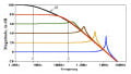
First, let’s take a look at the frequency-dependent behavior of an operational amplifier as an individual component. The following plot shows a typical frequency response for a general-purpose op-amp.
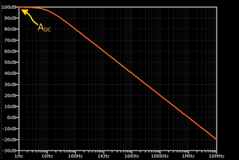
At very low frequencies, the op-amp applies the maximum open-loop gain, which we can call ADC to distinguish it from the gain at higher frequencies. As frequency increases, gain decreases, with the prominent transition from stable gain to decreasing gain occurring at the corner frequency, which in this case is 10 Hz. Eventually the slope stabilizes, and the gain decreases by 20 dB for every factor-of-10 increase in input frequency.
You might be wondering why the gain begins to decrease at such a low frequency. It turns out that designers intentionally create this type of frequency response because it makes the op-amp less likely to oscillate when used in a negative-feedback configuration (for more information on amplifier stability, please refer to Negative Feedback, Part 4: Introduction to Stability). This technique is called [[frequency compensation]], and when it is incorporated into the circuitry of the op-amp itself, the resulting device is called an internally compensated op-amp.
Calculating Open-Loop Gain
Because the op-amp’s gain is now a value that varies according to frequency (denoted by f), we can write it as A(jf) instead of simply A. This indicates that the gain is no longer a constant value, such as \(10^6 \). Instead, the gain is a function that has different values for different frequencies.
The frequency at which the op-amp’s gain reaches 0 dB is called the unity-gain frequency (denoted by \(f_t\)).
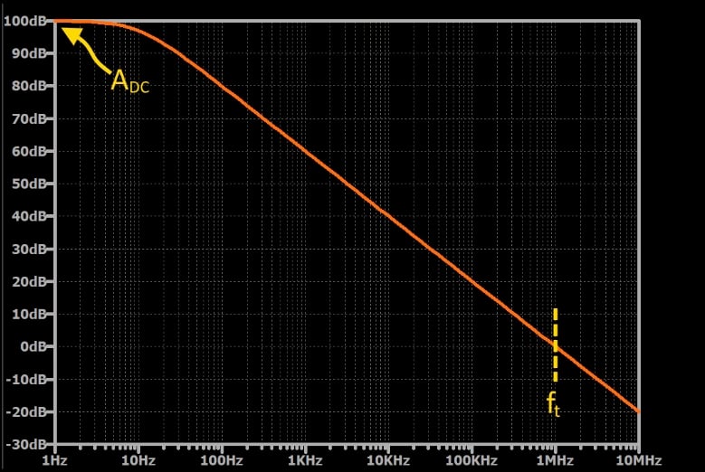
This value tells us the frequency at which the op-amp stops functioning as an amplifier, and it also gives us a convenient way to calculate the op-amp’s open-loop gain at a given frequency. As shown in the following equation—which is an approximation that is valid for frequencies significantly higher than the corner frequency—the gain is equal to the unity-gain frequency divided by the frequency of interest:
\[\left | A(jf)) \right | = \frac {f_t}{f}\]
Op-Amp Closed-Loop Frequency Response
An op-amp starts to lose gain at a low frequency, but because its initial gain is so high, it can still function as an effective amplifier at higher frequencies.
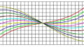
In fact, by using the op-amp in a negative-feedback configuration, we can “trade” gain for bandwidth. The gain of the overall amplifier doesn’t have to start decreasing at 10 Hz, because the required gain may be much lower than the open-loop gain of the op-amp. For example, if we want to implement a non-inverting amplifier with a gain of 2 V/V, the corner frequency of the closed-loop gain will be much higher than the corner frequency of the op-amp’s open-loop gain. As shown in the plot below, the curve representing closed-loop gain stays approximately flat until it approaches the curve representing open-loop gain:
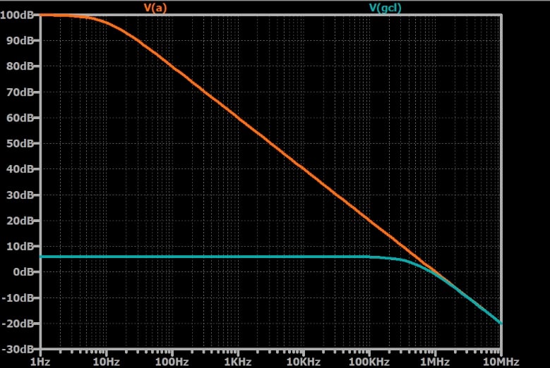
[[In the final image, “V(a)” should be “A(jf)” and “V(gcl)” should be “\(G_{CL}\)”]]
If we design the circuit for higher amplification, the curve representing closed-loop gain will approach the curve representing open-loop gain at a lower frequency—in other words, the closed-loop bandwidth will be narrower. For example, in the next plot, the closed-loop gain has been increased to 10 V/V.
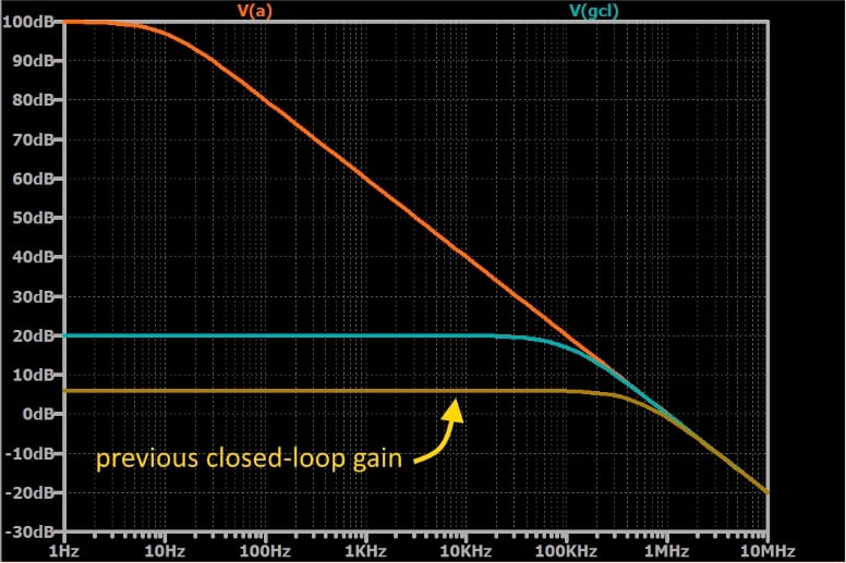
[[In the final image, “V(a)” should be “A(jf)” and “V(gcl)” should be “\(G_{CL}\)”]]
That’s how the trade-off works: the overall circuit can have less gain and more bandwidth, or more gain and less bandwidth.
Summary
- Real op-amps cannot apply the same gain to all input frequencies. Higher frequencies receive lower gain.
- Most op-amps are internally compensated. This reduces their bandwidth, but the overall effect is beneficial because frequency compensation makes them less susceptible to problematic oscillation.
- The frequency response of an internally compensated op-amp resembles that of a first-order RC low-pass filter.
- The use of negative feedback allows us to create amplifiers that trade gain for bandwidth.
Related Content


50 years ago (1970) we were amazed by the then new Operational Amplifier. Your description of the trade-off gain-bandwith still hold true now. When we designed analog avionic signal processors with Op-Amps, the first worry was always the risk of oscillation. Thus managing the signal phase was always our primary concern. Michel Virard - former design engineer at Canadian Marconi.