Facebook
 Google
 GitHub
 Linkedin
PLL Frequency Multiplication: Transient Response and Frequency Synthesis
Does the addition of a feedback divider affect PLL transient response? We’ll look at this question and other frequency-multiplication topics in this article.
Does the addition of a feedback divider affect phase-locked loop (PLL) transient response? We’ll look at this question and other frequency-multiplication topics in this article.
Supporting Information
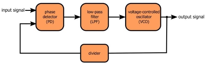
- What Exactly Is a Phase-Locked Loop, Anyways?
- How to Simulate a Phase-Locked Loop
- Understanding Phase-Locked Loop Transient Response
- How to Optimize the Transient Response of a Phase-Locked Loop
- Designing and Simulating an Optimized Phase-Locked Loop
- Understanding PLL Applications: Frequency Multiplication
In the previous article on frequency multiplication, we saw that a phase-locked loop can produce an output waveform with a frequency that is higher than the frequency of the input (AKA reference) signal. This is achieved by including a divider in the feedback loop.
This higher-frequency signal “inherits” desirable characteristics (i.e., frequency precision and stability over time and temperature) from the input waveform. Consequently, a low-quality voltage-controlled oscillator in conjunction with a high-quality (but low frequency) reference signal can produce a high-quality, high-frequency waveform.
Back to Transient Response
We’ve already discussed PLL transient response and, more specifically, how to design a PLL that has a desirable damping ratio. The following plot gives you an example of a PLL control voltage that settles quickly and smoothly on the final value:
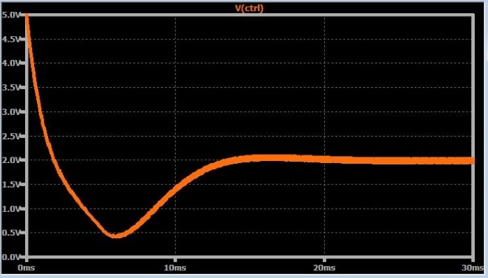
The next plot shows the control voltage for the exact same circuit, except that I have added a divide-by-two counter into the feedback loop.
This doesn’t look terrible, but something has definitely changed. Furthermore, the control voltage doesn’t reach a stable condition—you can see the periodic variations in the ripple amplitude.
If we zoom in and look at the input and output waveforms, it’s clear that we have a more serious issue:
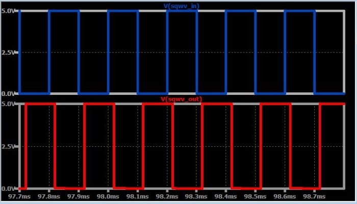
The output frequency (fOUT) is definitely not twice the input frequency (fIN). The problem here is that the VCO’s initial control current is not close enough to 2fIN; in other words, it is impossible for the control voltage to adjust the VCO frequency all the way to 2fIN.
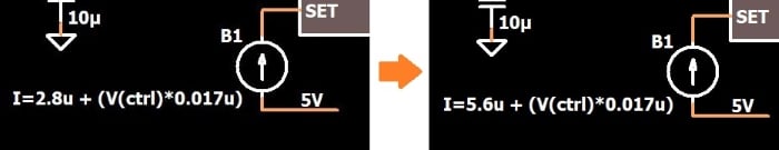
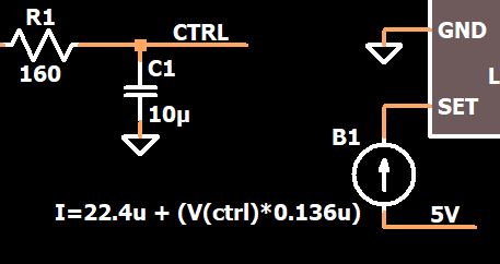
So the first thing we need to do is double the current source’s offset; this will bring the initial control current to a value that produces an fOUT that is in the vicinity of fIN.
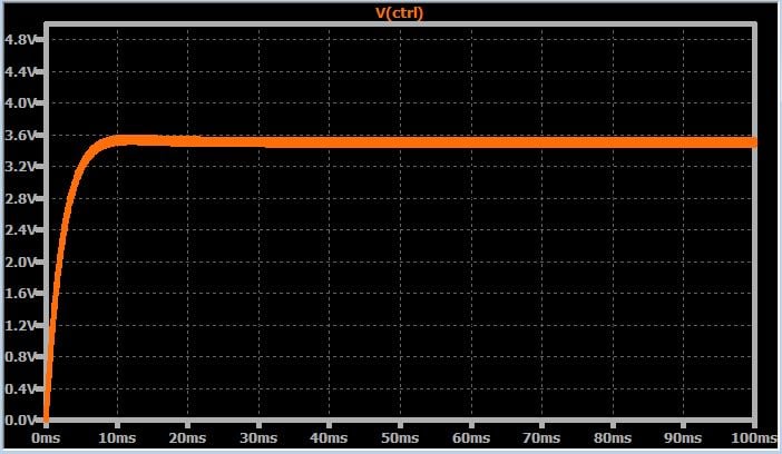
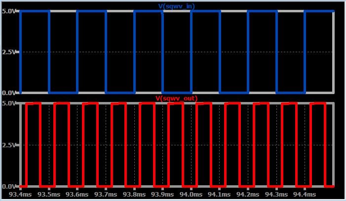
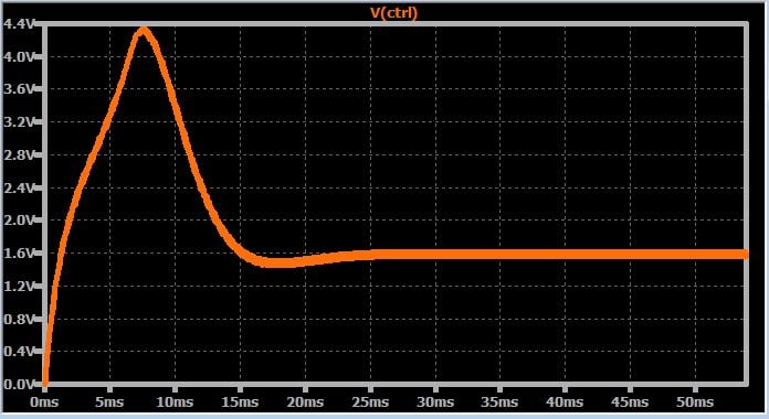
As shown by the following two plots, the PLL is working quite well now. The transient response exhibits good damping and fOUT = 2fIN.
Multiply Frequency, Multiply Gain
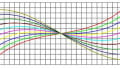
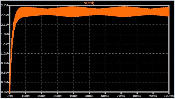
Unfortunately, this last set of simulations has deceived us. The PLL is working well, yes, but that’s only because the multiplication factor (denoted by N) is so low. When N = 2, the transient response is still quite good, but if we add more divide-by-two counters so that N = 8, the hidden problem is revealed:
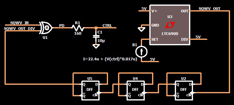
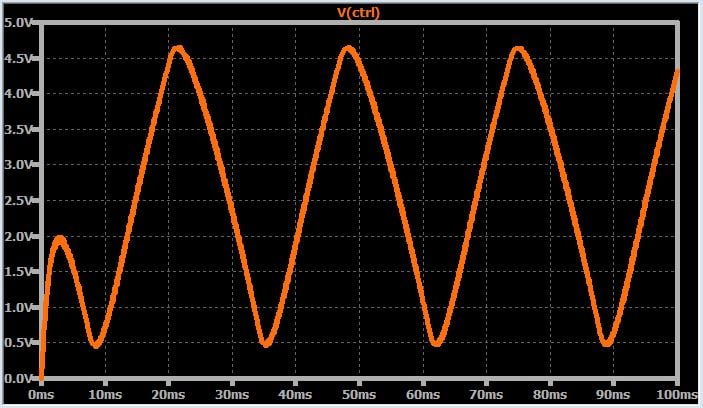
This is definitely not what I would call a critically damped transient response. In fact, it looks like the PLL will never achieve lock. This really isn’t surprising, though, if we take a step back and think about the effect of the divider. We know from previous articles that the damping ratio is influenced by K, which I described as the overall gain of the system, i.e., the gain of the phase detector multiplied by the gain of the VCO. But a more precise description of K is the “loop” gain, and the feedback path is of course part of the loop.
In a basic PLL, the feedback path has no effect on K because it is just a direct connection; thus, K = KPD × KVCO. But now we have a divider in the feedback path, such that the overall gain becomes
$$K=\frac{K_{PD}\times K_{VCO}}{N}$$
The bottom line here is that we no longer have a good damping ratio because the loop gain has changed. Fortunately, the remedy is simple: we multiply the VCO (or the PD) gain by N to compensate for the division by N. As you can see in the new control voltage plot, the desirable transient response has been restored.
Frequency Flexibility
At this point, we have a good idea of how to multiply an input frequency using a PLL and how to modify the circuit so that the frequency “gain” will not ruin our transient response. Currently, though, the system’s functionality is somewhat restricted.
Let’s say we spent good money on a very high-quality 1 MHz crystal-based oscillator and then went to the trouble of designing a fabulous PLL so that we could generate a variety of frequencies from this reference clock. With only a divider in the feedback path, though, the frequency options are rather limited: 2 MHz, 3 MHz, 4 MHz, etc. And, actually, if we implement the division with cascaded divide-by-two flip-flops, we’re limited to 2 MHz, 4 MHz, 8 MHz, etc.
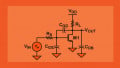
This might be acceptable in some applications, but if you want more flexibility, you can include a divider in front of the phase detector:
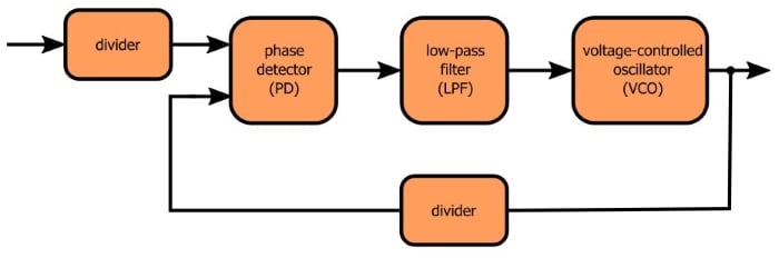
Now we have NINPUT and NFEEDBACK. The PLL’s input frequency becomes fREFERENCE/NINPUT, and then this frequency is multiplied by NFEEDBACK. Thus,
$$f_{OUT}=\frac{f_{REFERENCE}}{N_{INPUT}}\times N_{FEEDBACK}=f_{REFERENCE}\times\frac{N_{FEEDBACK}}{N_{INPUT}}$$
As you can see, we now have the ability to multiply the reference frequency by fractions instead of only integers.
You may have heard the term “fractional-N PLL,” and it would be perfectly understandable if you were to assume that this refers to the divide-then-multiply architecture shown above. Such is not the case, though. Fractional-N PLLs are based on a more complicated technique in which the divider value varies between N and N+1 in such a way as to create an average divider value equal to N plus a fraction. This process results in undesirable modulation of the VCO frequency, but the negative effects of this modulation can be mitigated by randomization and noise shaping.
Conclusion
We discussed the effect of frequency “gain” on PLL transient response, and we saw that a proper damping ratio can be restored by increasing the VCO gain. With regard to frequency synthesis, we now know that a divider (placed before the phase detector) can expand our frequency-multiplication options. We finished with a brief explanation of the fractional-N architecture. Perhaps we’ll take a closer look at fractional-N PLLs in the future; honestly, though, I might be burned out on PLL articles by the time I’m ready to tackle that topic.
If you want to do some PLL experimentation on your own, feel free to save yourself a bit of time by downloading my LTspice schematic (just click on the orange button).
PLL_frequency_multiplication_2.zip
Related Content