 Facebook
 Google
 GitHub
 Linkedin
Negative Feedback, Part 4: Introduction to Stability
Why are negative-feedback amplifiers susceptible to oscillation? What is the fundamental criterion for stability? Let’s find out.
Why are negative-feedback amplifiers susceptible to oscillation? What is the fundamental criterion for stability? Let’s find out.
Previous Articles in This Series
- Negative Feedback, Part 1: General Structure and Essential Concepts
- Negative Feedback, Part 2: Improving Gain Sensitivity and Bandwidth
- Negative Feedback, Part 3: Improving Noise, Linearity, and Impedance
Supporting Information
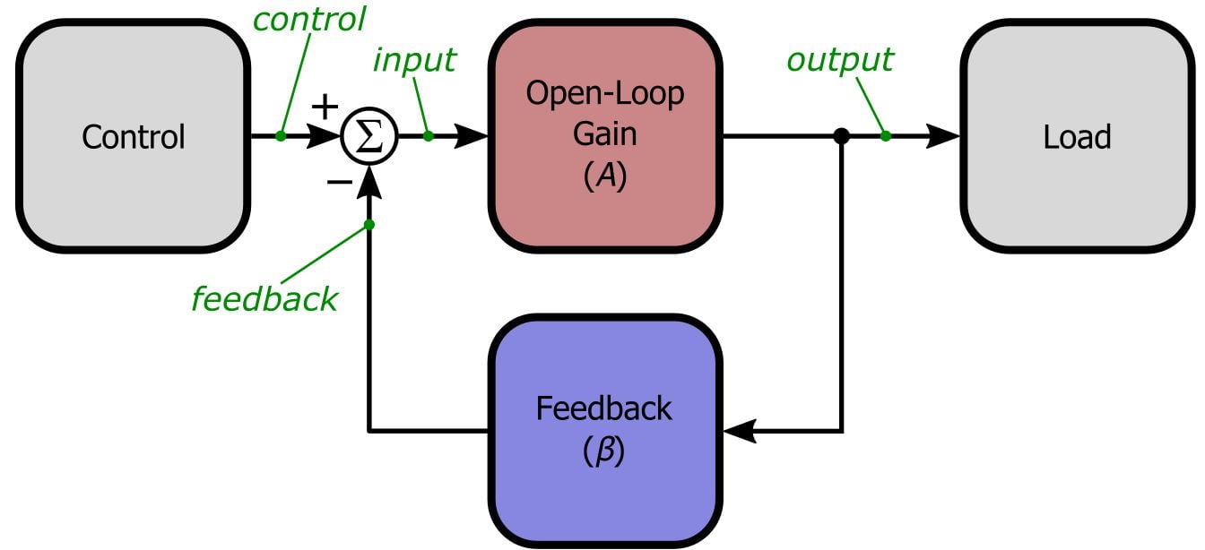
Just so you don’t have to switch pages every time you want to ponder the general feedback structure, here is the diagram presented in the first article:
No Free Lunch . . .
The previous articles in this series have demonstrated that negative feedback is a simple, inexpensive technique that allows us to greatly improve the performance of amplifier circuits. At first it seems like we are getting something for almost nothing, until we recall that all these benefits come at the cost of reduced gain. However, that extra gain is readily available from standard semiconductor devices, and furthermore, we usually don’t need or even want all that gain. So again we appear to be getting something for almost nothing, and thus all but the most devoted optimists might be growing suspicious. Surely there is some other disadvantage, you say, something else that we lose when we add that seemingly beneficent negative-feedback network. Well, your intuition serves you well, for if we are not careful we will lose something quite important indeed: stability.
The many benefits of negative feedback will be quickly forgotten and despised when you notice that your amplifier has turned into an oscillator. In a way, though, catastrophic oscillation is not so bad, because the problem is obvious. Marginal stability, which leads to excessive ringing in the time domain and peaking in the frequency domain, can be an elusive troublemaker. Even worse, a marginally stable circuit may be functional during testing but useless when the amplifier is exposed to different operational or environmental conditions. Thus, it is critical that we thoroughly understand why negative feedback can lead to oscillation and how to ensure that the amplifier will amplify, not oscillate.
When Negative Becomes Positive
It should come as no surprise that positive feedback can lead to oscillations: 1) apply an input signal 2) amplify the input signal 3) feed the amplified output back and add it to the input 4) the input is now larger, and this larger input is amplified 5) the amplified output is again fed back and added to the input 6) the input is larger again, gets amplified again, receives positive feedback again, and so on. Clearly, this is an “unstable” situation—the output will rapidly increase until it is limited by some external condition (usually the power supply voltages).
But why would negative feedback ever cause oscillation? By subtracting the output from the input, we are ensuring that increases in the input signal always lead to counterbalancing decreases via feedback. There is just one catch: if an AC signal experiences a 180° phase shift before being fed back and subtracted, our negative feedback has just become positive.
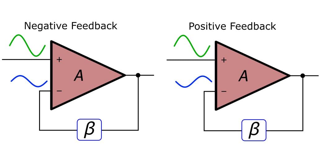
In the left-hand diagram, we are subtracting a positive number from a positive number and a negative number from a negative number. This is indeed subtraction. In the right-hand diagram, we are subtracting a negative number from a positive number and a positive number from a negative number. This is no longer negative feedback—the magnitude of both positive and negative numbers is increasing.
The Loop Gain
The quantity that directly determines whether a negative-feedback circuit is stable is not the closed-loop gain or the open-loop gain, but rather the loop gain, written as Aβ. Recall our formula for closed-loop gain:
\[G_{CL}=\frac{A}{1+A\beta}\]
This formula assumes that Aβ is a positive number (because positive Aβ means that the feedback is negative). What happens when Aβ is not positive? Consider the case when Aβ = -1:
\[G_{CL}=\frac{A}{1+\left(-1\right)}=\frac{A}{0}=\infty\]
In this context, a closed-loop gain of infinity corresponds to an oscillator—even with zero input the output is saturated. Thus, the critical quantity in stability analysis is the loop gain.
It is essential to develop a solid conceptual understanding of why stability problems occur and how to prevent them. This question-and-answer sequence should help to address some of the prominent points of confusion.
Q: Where does this phase shift come from? I didn’t ask for any phase shift in my amplifier.
A: Remember, all amplifiers will eventually exhibit gain roll-off at high frequencies. Internally compensated op-amps begin to roll off at very low frequencies. In any event, this roll-off is caused by poles somewhere in the circuit, and poles always bring phase shift as well as decreasing gain.
Q: OK, so I have phase shift. But all of my op-amp circuits are intended for DC or low-frequency applications. There won’t be much phase shift for my signals, so I don’t have to worry about stability, right?
A: Good question. Unfortunately, the frequency of your signal-of-interest is largely irrelevant. Real-life signals always have noise, and some of this noise will be at high frequencies. Also, any spurious voltage transient contains high-frequency energy. Remember, with enough phase shift we are dealing with positive—i.e., regenerative—feedback. Even when these inescapable high-frequency components are of very low amplitude, if your circuit is not inherently stable the regenerative nature of positive feedback will increase their amplitude until oscillations become apparent.
Q: It’s hopeless, then! Amplifiers always exhibit phase shift at high frequencies, and signals are always subject to high-frequency components—so how can a circuit ever be stable?
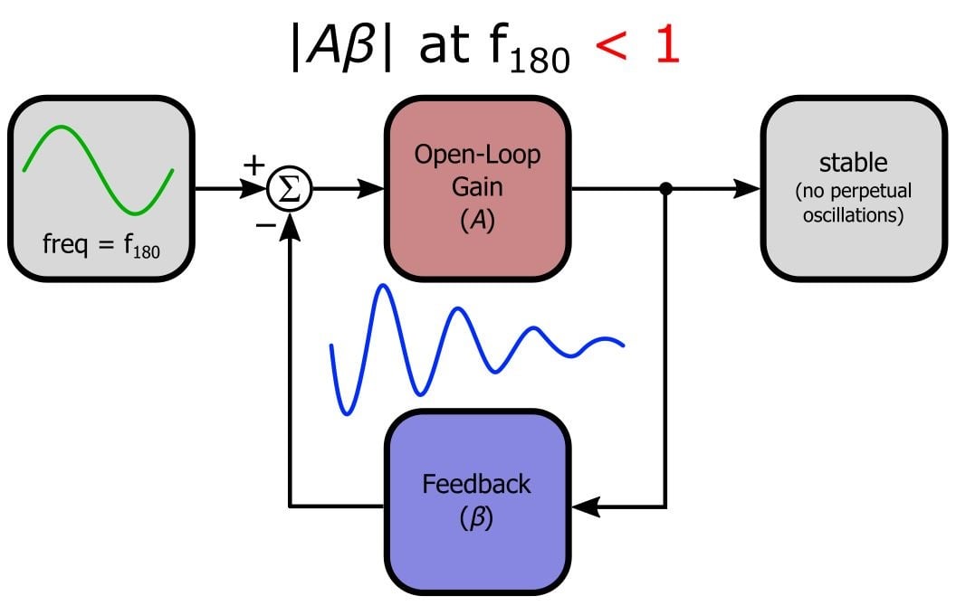
A: Don’t despair—this is where the loop gain comes in. Think about the general feedback structure: any signals traveling around the feedback loop are multiplied by A then β. This is why we call Aβ the “loop” gain. If Aβ is less than unity at the high frequencies where phase shift reaches 180°, the high-frequency phase-shifted signals will gradually fade away instead of progressively building up into major oscillations. Make sure you understand this. Picture little sine waves traveling through the Aβ loop: If Aβ is greater than unity, the sine waves will build upon each other every time they go through the loop, and their amplitude gradually increases because Aβ is amplifying them. If Aβ is less than unity, the signals will be gradually attenuated into insignificance despite the fact that they are reinforcing each other at the “subtraction” node.
The Stability Criterion
Now we can explicitly state the theoretical stability criterion, where “loop gain” refers to the frequency response of the open-loop gain multiplied by the frequency response of the feedback network (i.e., loop gain = Aβ analyzed as a function of frequency): if the loop gain’s magnitude is less than unity at the frequency where the loop gain’s phase shift is 180°, the circuit is stable. In practice, the loop gain must be significantly less than unity at this frequency to avoid marginal stability.
Conclusion
Now we know why negative-feedback amplifiers are susceptible to oscillation and what condition must be present to ensure stability. But there is much more to the stability story, as forthcoming articles will demonstrate. In the next article we will employ frequency-domain simulations to further understand loop gain. We will also discuss gain margin and phase margin, which are two closely related parameters used to assess an amplifier’s degree of stability.
Next Article in Series: Negative Feedback, Part 5: Gain Margin and Phase Margin
Related Content


Hi, I do not fully understand why at 180 degree the A beta gain have to be smaller than one. A loop gain smaller than one still is go to add and add to the input signal and is because the the sign is not changed. I am wrong? please help me
@Pablo
I’ll try… Let’s start again from normal operating condition. Suppose at first that input signal is 0, output signal is 0. Positive input start to rise, so, differential input rise, output rise, ad negative input also rise reducing the input: next stable condition is reached when differential input is quite 0 (negative input is as positive input), or more exactly when differential input Vin =V+ - V- = Vo/A (note: Vin is NOT your signal, is the “error signal”, and for large A is strongly closed to 0).
Ok, same start conditions but consider phase inversion and a gain greater than one. Positive input rises a little, output rise, negative input decrease increasing even more the total differential voltage (Vin) at the input of the amplifier, this causes an even more bigger output that feed back into an even bigger input and so on, clearly an instable configuration.
Last one. Phase inversion and a loop gain A*B less than one. As before, at first everything is 0. Positive input start to rise, let say it rise 1 just for reference, negative input start to go down: as oscillating amplifier, feedback rise the input voltage difference even more than the positive input alone. Suppose negative input goes down to -1, differential input is now -2. But if AB is 0,5 this is a stable condition, in fact Vin * AB = 2*0.5 = V- = -1! The differential input Vin come back to the input as a lower voltage and so is stable! Last one think, if you feel comfortable with digital circuits let’s break into discrete step the whole process. T=0 since V+ = V- = Vo = 0. Next step is V+ = 1, T=1, the same is written as V+[1]=1. Next step, V+ propagates through the loop, V-[2] = (V+[1] -V-[1])AB, in the next iteration V+ - V- is called Vin[1], as input changes AB is always the open loop gain we assume is less than 1 say 0,5, so here is some of the following steps:
Vin[1] = 1; V-[2] = Vin[1] AB = -0.5
Vin[2] = 1.5; V-[3] = Vin[2] AB = -0.75
Vin[3] = 1.75; V-[4] = Vin[3] AB = -0.875
…
Vin[n] = 2; V-[n+1] = Vin[n] AB = 2*0.5 = 1
Vin[n+1] = 2; <- Nothing changes!
Bye bye