 Facebook
 Google
 GitHub
 Linkedin
An Introduction to Negative Impedance Converters
An introduction to the properties and purposes of a negative resistance device. Later articles will extend to negative impedances and some applications.
An introduction to the properties and purposes of a negative resistance device. Later articles will extend to negative impedances and some applications.
Recommended Level
Beginner
Introduction
We all know Ohm's law. V = IR. A simple equation that is the cornerstone of electronics. But what if we weren't constrained by this rule? What if we could do the exact opposite, and make a device that had the property V = - IR? Voltage increases as the current increases going the other way. What would that imply about the device, how it works, how it could be used, and if it is even possible to create one in the lab? Let's answer these questions and discuss the principles of negative resistance (and later, impedance) converters.
The Negative Resistance Converter
The consequences of a device that could have this property are puzzling. All ordinary devices have some internal resistance inherent to their construction that automatically dissipates energy when a current is flowing. Ordinary resistors, which obey Ohms law in a simple way, drop a voltage across their terminals when a current flows and dissipate power that is lost as heat, according to the well known equation P = IV. When a current is pushed through a resistor, a voltage is dropped across the resistor and heat is still lost through the same mechanism. However, when our hypothetical device, which we will call a negative resistance converter, or NRC, has a voltage drop across it, a current flows through it in the opposite direction: from low to high voltage. Equivalently, when a current is flowing through the device, a negative voltage difference will be observed. This directly defies our intuition about how electrical devices work. We can place a voltage across an object and get current flowing in the wrong direction. V= - IR. But how does it work, and why does this happen? What is the equation for the power it dissipates? This wacky device will require some further investigation to discover the underlying operation of this circuit.
Below is a circuit diagram of a very basic NRC. Hopefully you are familiar with operational amplifiers and can recognize the simplicity of the circuit: a one port device containing only an op-amp and three resistors. Applying the basic rules of circuits to the properties of resistors and op-amps, we see how this device produces the opposite of what is typically expected. We will apply a positive voltage at the voltage in terminal, and ground the bottom of the circuit to zero volts. What happens? There should be a current upwards from ground to the positive voltage, which is the exact opposite of our intuition about electric circuits, but we will observe that it arises naturally from our basic rules about circuits. We can use V = IR and Kirchhoff's laws to demonstrate how this electric device, as a whole, has the property of V = -IR.
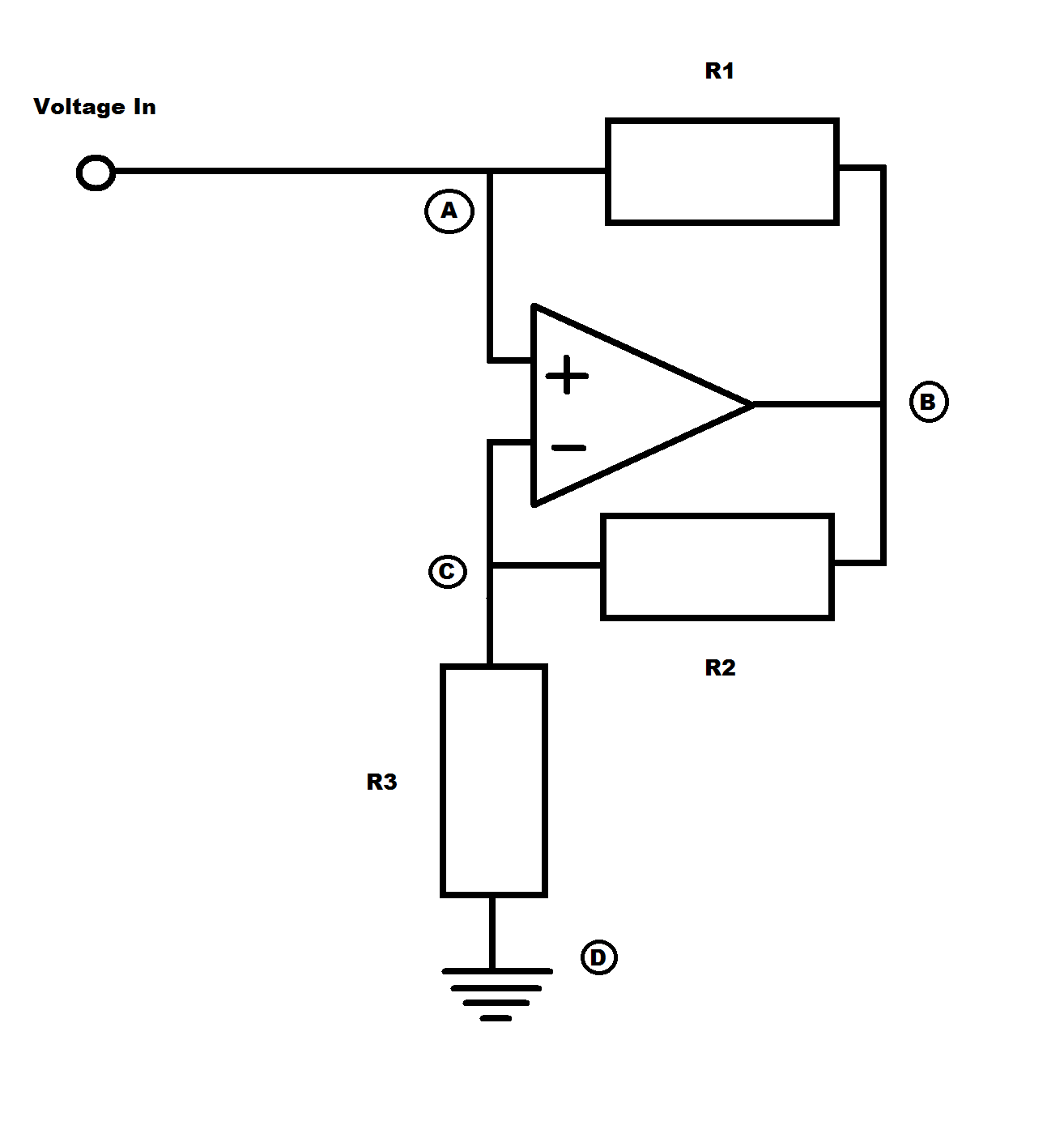
Let us define a current that is going the 'traditional' route from the voltage input down to the ground. We will call the first branch of the current I1, which passes through R1 going to the right, and the second branch will be I2, which passes through R2 going to the left, and through R3 going downwards. No current flows into or out of either input terminals of the op amp, and the voltage at both inputs is the same. With these conventions set, we can see that there is only one unknown voltage within the circuit. The voltage at point A is whatever input voltage we apply, the voltage at point D is simply the ground voltage, and the voltage at point C is always the same as the voltage at point A due to the properties of op-amps. This is a critical piece of information, because the entire purpose of the op-amp is to drive a current from its output to make its two input terminals the same voltage. All we need to do is find the voltage at point B in order to figure out what's going on within this circuit.
To do so, we will start with the current through R1,
$$I_{1} = \frac{(V_{in} – V_{oa})}{R_{1}}$$
noting that Voa is the voltage at point B, the output of the op-amp. The second current in the circuit is
$$I_{2} = \frac{(V_{oa} – V_{in})}{R_{2}}$$
or, because that current then flows through R3,
$$I_{2} = \frac{V_{in}}{R_{3}}$$
Now after manipulating these equations using a moderate amount of algebra and letting R1 = R2 for simplicity we get that
$$V_{in} = - I_{1}R_{3}$$
Because we established our input voltage as positive and our current I1 as positive when going down from Vin to ground, we know that there is a negative current going from Vin to ground so long as R3 is a positive resistor. This implies that the direction of the current is actually from ground to the voltage input.
So by applying a positive voltage to Vin, we will see a current coming up from ground and out to the voltage input. What gives? I haven't made a math error. There are no tricks here. This actually happens. You can hookup a positive voltage to the terminals of our circuit and put an ammeter in series with our circuit and you will see a negative number on the ammeter in the lab. If you have the equipment at home, go ahead and try it out. The only necessary equipment are a power supply, a multimeter, three resistors, an op-amp such as an LM741, and some hookup wire. Unfortunately, there is no free energy. Not even our mythical negative resistance converter can avoid that. It takes a power supply to run the converter device. Inside is an amplifier that takes in energy from some external power source and supplies it to our device. But the device we have created has some very interesting properties due to its tendency to force current to go the wrong way. For example, the power dissipated in this part of a circuit is negative. This means that an NRC pulls in power to the circuit, or energy, rather than dissipating it like a resistor. The NRC works like a power supply in this manner.
So now that we can create an NRC and test it and truly understand how it works, what could we even use it for? It turns out that the device we have just discussed has practical applications in power supplies and many basic circuits. All power sources, including voltage- and current-regulated supplies have some internal resistance. The simplest case are chemical batteries, which usually have a few ohms or a few dozen ohms of resistance in series with the battery. By finding out the exact value of this resistance through some simple laboratory tests, you can then design a negative resistance converter in series with the battery that will cancel out this positive resistance with a negative resistance. The end result is a combined circuit that acts much closer to an ideal voltage source, without changing its output when the load changes. Even current sources have a parallel resistance internal to them, which can be removed by placing an NRC in parallel with the current source. There are some caveats, such as the fact that another power source must be used to power the op-amp in the NRC. However, setting up a circuit in this manner can allow for a more flexible and ideal design that won't fall apart when you need a very finely tuned power source that does not change its output with the load resistance.
Yet can we do even more? Persisting minds might imagine that we could extend these ideas to any impedance. But can we? How would that work? A negative capacitance would be an inductance, and a negative inductance would be a capacitance. The technical details of how this works out are fascinating, but involve lots of complex arithmetic and understanding of AC signals, which I want to save for another time.
The reality of the situation is that we get another practical application of NRCs by considering them as negative impedance converters, which we should probably start calling NICs. We can put a capacitor of any size in for R3 and we would discover that our device now acts, in many ways, like an inductor. Why would we do that? Because inductors are big and bulky and can cause electromagnetic interference elsewhere in our circuits. But, by using an NIC to make a device that works like an inductor we can eliminate those nasty side effects and get a simulator inductor that could be much smaller and cause less problems in the circuit.
Of course, there are some trade-offs due to the increased cost of using an NIC to make an inductor and having to supply power to what would otherwise be a passive device, but overall we have discovered a novel use for a few resistors, a capacitor, and an op-amp that improves our ability to define new circuits and alter existing ones. We can extend the idea of an NIC to many different concepts, and the configurations of passive components used to replace R3 are as infinite as the imagination of the inventor using it.
Related Content


Thanks for sharing this !!!
Your statement: “So by applying a positive voltage to Vin, we will see a current coming up from ground and out to the voltage input. What gives?” Current flows normally from neg to positive. I don’t understand your question “what gives?”.